


Editor-in-Chief
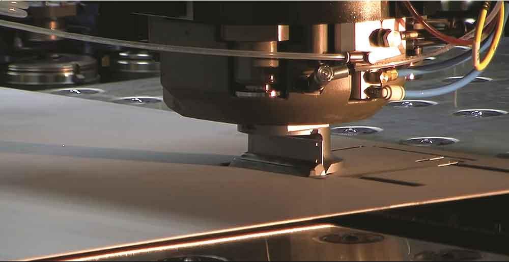
Forms on a punching machine can now be as tall as 0.75 in.
The explosion of fiber laser cutting machines over the last decade has forced people to rethink their fabrication operations. Laser-cut parts are produced at rates that can easily create a backup in the bending department that doesn’t have the latest press brake technology or might be understaffed. It can be hard for a shop to keep up.
In some ways, that’s motivated some fab shops to look at the punching machine from a different perspective. Fabricators are seeing that a lot of forms can be made on a punching machine, creating a piece that can go straight to deburring or painting and out the door to the customer. You can have those parts bypass the bending department completely, eliminating the frustrating scene of having laser-cut parts sitting on a pallet in front of the press brake waiting for someone to get to it.
What type of forms can be done on the punching machine? Let’s look at some of the ways that fabricators are discovering more versatility in their punching machines.
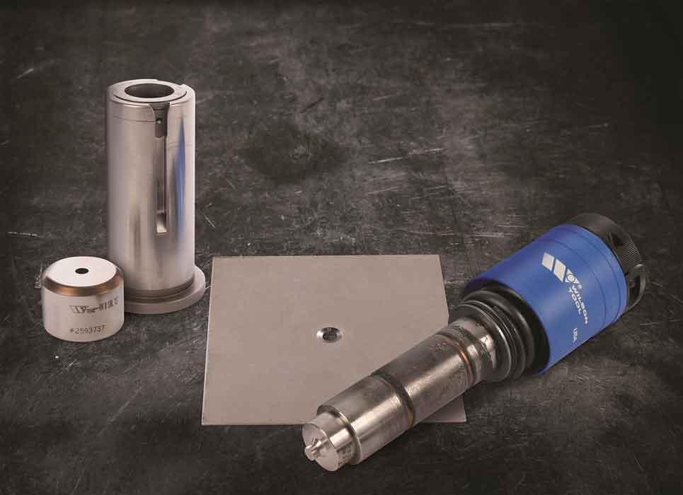
If you have ever had to create a countersink manually, you are familiar with the three-step process: punch the hole, drill the sink, and deburr. The process is time-consuming and inconsistent.
Forming a countersink in the punch press delivers a consistent shape that meets specs and doesn’t require any secondary cleanup. (The forming process begins with a prepunched hole in the sheet before running the countersink.) It can cut the production time of countersinks dramatically when compared to a manual process.
Two approaches can be taken when forming countersinks in the punching machine:
Keep in mind that relying solely on coining tooling to create these countersinks can be an issue if the tooling is paired with a punching machine in the 20- to 30-ton range. Unlike their older counterparts in the 50-ton range, newer machines might not generate the tonnage needed.
If the material is too thick, an underpowered punching machine drives that coining tool just enough to get close to the original specifications. For instance, if you wanted a countersink with a 0.500 in. OD and a 0.300 in. ID in this underpowered scenario, it might end up only with a 0.550 in. OD and a 0.350 in. ID. No damage is done to the tooling or the punching machine. The material just doesn’t flow enough because the machine didn’t have enough tonnage.
Countersinking on a punching machine keeps a fabricator from having to worry about excessive material handling and the deburring that comes with manually creating countersinks.
That’s why more metal fabricators are turning to the forming tools. They have open ends on them, giving the material somewhere to go. The tool is actually flowing the material down to fill in the hole.
For the sake of flexibility, both coining and forming countersink tools are available with interchangeable inserts for fast size changes.
It’s no secret that if manufacturers can justify using thinner materials in their product designs, they choose to do so. For many, it’s just the economical thing to do. Others may be concerned with eliminating weight.
One of the easiest ways to strengthen thin sheet metal is the introduction of a rib. A wheel tool inside the punching machine is one of the easiest ways to create these ribs.
The sheet is pulled through the tooling, creating ribs quickly in any location on the sheet. Ribs can be straight, curved, or in any imaginable pattern on the sheet. In most cases, the arc needs to be at least 1 in.
This type of tooling produces forms with nearly no burrs or nibble marks. The alternative, tooling that comes down to create small segments of the rib with each hit, is likely to leave marks on the sheet as it progresses through the entire rib design.
It would be misleading to describe this wheel technology as new, but it’s safe to say that it is underutilized. The real challenge associated with it is that it takes a little bit of extra programming knowledge to produce suitable instructions for producing the ribs that go beyond a simple straight line. This is not just setting up parameters to punch a hole in the sheet metal.The wheel tooling can be used for other functions, such as knurls, offsets, logos, and shears.
Much like a stamping press and specialized tooling, punching machines can produce complete parts. Progressive tools, with four to six stations typically, can fit into 3½- or 4½-in. stations in a thick-turret punching machine and do the necessary punching and forming in one process.
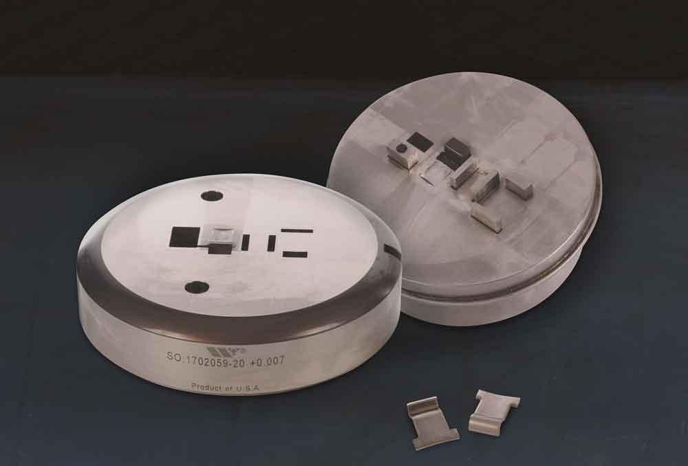
Progressive tooling can be used to form intricate metal parts on a punching machine.
Obviously, the type of part that can be made with these progressive tools can’t be too large. An electrical clip is a good example of an ideal size for these tools.
How does it work? In most instances, the first couple of stations in the progressive tool are used for prepunching. The sheet is then moved, and the forming stations are employed. When the part has progressed to the final station, the final cutoff occurs and the part is released into the slug chute or some other sort of exit point.
The exciting thing about this tool is its productivity. Once you have reached the final station of the tool, a final part is completed with every hit of the tool because each station is engaging the sheet metal with every stroke.
When it came to creating forms in older thick-turret punching machines, you had to ensure the form fit within a certain range. Those older machines typically had a feed clearance of 0.787 in. How did you get to that? You needed to take into account the die that was going to wipe the form up, which stuck up more than a piercing die, and the upper turret from where the punch comes down. That space between the upper turret and the top of the standard piercing die measured about 0.787 in. Once you added material and die add-on into this equation, you roughly had enough room to create a 0.50-in. form.
In some of the newer machines manufactured over the last 15 years, that window has increased to 0.984 in. Now forms can be created that are about 0.75 in. tall.
Imagine using that extra room to create 90-degree bends, like the ones found in a partial enclosure. Tooling, with a rotating cam built into it, actually performs like a press brake ram when the machine stroke is engaged, producing a 90-degree bend without marking the surface. The stroke can be repeated multiple times on the same part to create that partial enclosure.
Additionally, by adjusting stroke depth, the machine can produce other angles. With sheet movement and another hit after the initial hit of 90 degrees, the form can be bent over backwards to approximately 25 degrees. It’s just a matter of figuring out what type of tool is needed and what the final angle will be.
Of course, the window in a punching machine is somewhat limited for tall forms, but that still doesn’t prevent you from asking about forms that just aren’t a fit for even the most modern punch presses. That led punching tool designers to wonder how fabricators might be able to use the tooling to produce the much taller forms they needed to produce.
Well, the answer was on the press brake. An adapter that accommodates the punching tooling for a press brake was created. The same tool that goes into the turret slides into an adapter that then slides into the press brake. These can be built for all station sizes. (Guide pins ensure that the tooling and die match up inside the press brake window.) The press brake’s ram provides the downward pressure to engage the tooling and produce the form.
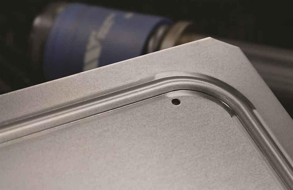
A rib like this can be created with a wheel tool on a punching machine.
Now you have a much larger area in which to create the form. That 9 in. to 12 in. of clearance between the brake’s upper and lower beam provides a lot more forming freedom that can be found on the punching machine. It may not be the first choice for a high-volume run, but it does provide the fab shop with some forming flexibility and the ability to use punching tooling that it already owns.
Dave Cormican is an applications engineer with Wilson Tool International, 12912 Farnham Ave., White Bear Lake, MN 55110, 651-286-6000, www.wilsontool.com.


The Fabricator is North America's leading magazine for the metal forming and fabricating industry. The magazine delivers the news, technical articles, and case histories that enable fabricators to do their jobs more efficiently. The Fabricator has served the industry since 1970.
start your free subscription
Easily access valuable industry resources now with full access to the digital edition of The Fabricator.

Easily access valuable industry resources now with full access to the digital edition of The Welder.

Easily access valuable industry resources now with full access to the digital edition of The Tube and Pipe Journal.

Easily access valuable industry resources now with full access to the digital edition of The Fabricator en Español.
In this episode of The Fabricator Podcast, Caleb Chamberlain, co-founder and CEO of OSH Cut, discusses his company’s...


