


Applications Technician
Poor edge quality on a punched part can have many causes, all of which should be considered before jumping to conclusions. Image provided by Mate Precision Technologies
Worldwide, CNC punch press operators produce millions, if not billions, of parts monthly. The process appears straightforward, but the subtleties abound. Sometimes part quality is affected by its finished edge.
How do you avoid producing parts with inferior punched edges? As with so many problems in metal fabrication, various factors come into play. The trick is to consider them all before jumping to a conclusion, taking corrective action, and discovering that your edge problem stubbornly persists.
When a visibly larger rollover appears on a part’s punch edge, it’s probably time to sharpen the tools. Sharpening tools regularly will help produce good-quality parts and help extend tool life. Tools should be sharpened when cutting edges are worn to a maximum radius of 0.010 in. (0.25 mm).
To inspect for this radius, hold the edge near a light source and look for reflections as the light bounces off the radiused edge. Also try the fingernail test: Lightly (and carefully) drag your fingernail across the edge; if that’s enough to lightly shave your fingernail, the punched edge is sharp and the tool has some life left. If you don’t see shavings, it might be time to sharpen your tool.
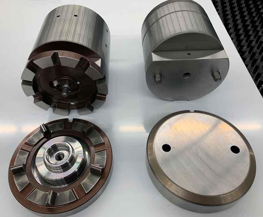
When sharpening tools, it’s best to remove a small amount of the tool surface more frequently rather than large amounts less frequently. Light, frequent sharpening helps extend tool life and improve part quality (see Figures 1 and 2).
After sharpening a tool on a tool grinding machine, use a sharpening stone to remove the small burr that develops on the punch point. Doing this will create a minimal radius, between 0.001 and 0.002 in., on the tool’s cutting edges.
The tools become magnetized when sharpened, so be sure to demagnetize them afterward. Forget this step and you might find punched slugs sticking to punch points and possibly ending up on top of the sheet, where the machine can press them into the sheet and create unwanted marks or dents. Slugs on top of the sheet and close to the punch point might result in a double material thickness being punched, which can damage the sheet and cause premature tool wear.
Uneven tool wear or excessive burrs along the punched edge might indicate that the station needs vertical alignment (see Figures 3 and 4). Vertically aligning tooling stations ensures that the punch pushes the material through the die opening with the same amount of clearance on all sides of the punch point.
Also check for radial alignment, which keeps edges and contours straight and uniform. Radial alignment refers to the rotation or angular setting of a station. A misaligned station angle can create stepped or uneven punched edges, as well as incorrect angles for shaped punches.
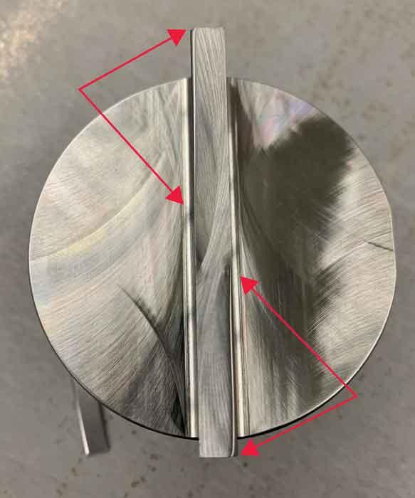
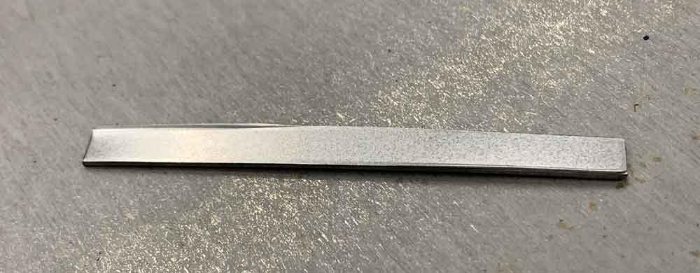
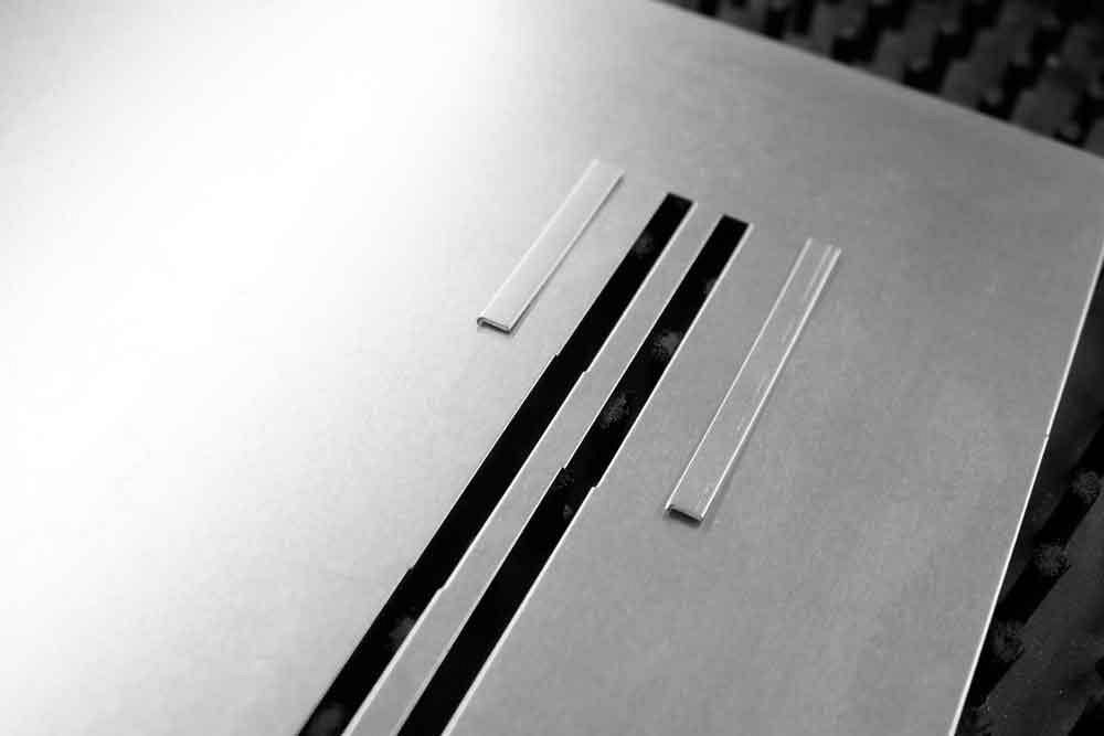
A slitting or parting tool (typically a long rectangle) in a station that’s out of radial alignment can produce jagged edges in the punched part, an effect known as sawtoothing, creating a small step at the end of every punch location along the edge. It’s a good indicator that you need to realign the station radially. The longer the parting tool, the more pronounced the step is (see Figure 5).
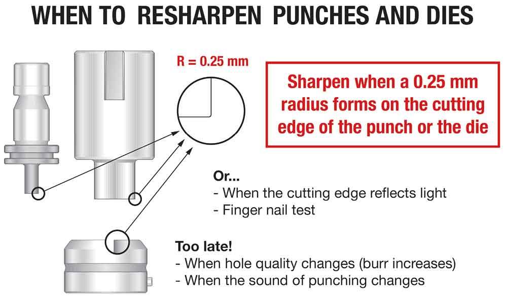
Figure 1
When edges have a radius greater than 0.25 mm, it’s time to sharpen both your punches and dies. (Click on figure for complete image.)
Every fabrication shop should have a good set of alignment tools for periodic punch station inspections and adjustments. Whether you’re using the standard two-pin variety or more elaborate LED tools, both are designed to align tools vertically and radially (see Figure 6). To set stations radially, you will typically need a magnetic-based dial indicator and a sturdy steel sheet, ideally 14 ga. or thicker, to traverse the indicator along a screw-on bar for the alignment tool to measure angularity.
With extreme deflection, or even just a little deflection when punching with very tight clearances, the punch point can actually contact the die edge on the open side of the material, damaging the worn cutting surface in that area. This can cause excessive or uneven burrs, as well as oblong or egg-shaped holes with round punches.
You can avoid nibbling by using specially shaped tools that match the contour being punched. Such tools will produce a better edge and reduce the number of hits required to punch a feature, which also reduces tool and machine wear.
If you can’t avoid nibbling, use fully guided tools, which can minimize punch deflection or eliminate it entirely. With multiple or extended guiding surfaces that control the punch-point position, fully guided tools can be ideal for nibbling applications and punching hole diameters smaller than the material thickness. That said, they might not be the best choice for punching soft materials such as aluminum or hard materials such as stainless steel—both of which are susceptible to galling, or a buildup of the punched material on the punch tip. Galling adds to the punch point’s overall diameter and decreases clearance between the punch and stripper (or the punch and die), which can lead to stripping issues, poor hole quality, and premature tool wear.
Lubricated punch pads, which provide lubrication on the punch tip, can also help reduce or eliminate galling. All of these products will increase tool life and improve tooling performance.
Stripping errors could be caused by worn, damaged, or broken springs in the punch assembly. Although these springs are durable, they may wear over time. If springs are fatigued, cracked, or broken, they should be replaced.
Keep interior punch components clean and well-lubricated. Dirty or dry tooling components—such as the punch body, guide body, guide interior, and turret bore (if applicable)—prevent the springs from performing to their ability and can lead to stripping issues.
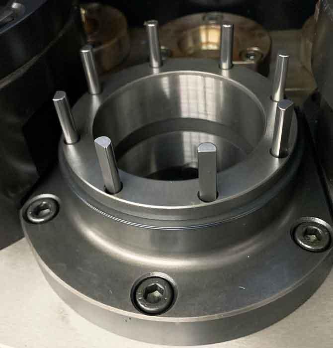
If you have turret presses, make sure lifting pins and lifter springs are straight and undamaged (see Figure 7), and replace them if they’re worn or damaged. Worn or damaged turret keys should also be replaced and aligned when needed.
Because dull tools also can contribute to stripping problems, keep tools sharp and clean. If you are punching heavy or thick material and experiencing stripping problems, consider using heavy-duty tool configurations.
Proper clearance between the punch and die is essential. If the die clearance is too tight, the resulting hole may be good, but the force required to create that hole increases, and stripping becomes difficult. All this generates more heat, which fosters galling on the punch point. At the other extreme, excessive die clearance causes more rollover, or rounded top edges, in the punched part, and increased cracking and fracturing create rough edges and large burrs.
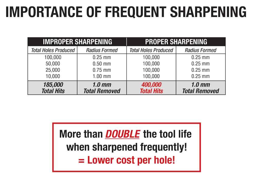
Figure 2
Proper sharpening can increase the total number of hits you can get out of a tool. (Click on figure for complete image.)
Consider a tool steel’s material composition and know that not all tool steels are created equally. M2 high-speed steel has poor toughness but good wear resistance. A2, an air-hardened tool steel, has good toughness and fair wear resistance. D2, a high-carbon chromium steel, has fair toughness and good wear resistance. S7, a shock-resisting tool steel, has exceptional toughness but poor wear resistance. PM-M4, a powdered-metal tool, has excellent abrasion resistance and fair toughness.
C-frame machines have the ram at the top and end of the frame, while O-frame systems have the ram centered within the frame. If processing thicker or heavier material, or if you have high-tonnage applications, you might consider a portal-frame machine. The O-style frame helps prevent deflection or distortion when punching. Higher-tonnage hits might deflect in a C-style machine, where more flexing of the frame is possible.
Poor edge quality can have many root causes. Poor tool sharpening and maintenance practices might be to blame, but you might find other culprits too. Your machine might be out of alignment. You might need special-shape tools or tools with treatments or coatings. The tool steels in your punches and dies might not suit the application. The machine’s design, including its frame type, also can factor into the equation.
If edge problems persist, try not to jump to a conclusion without first considering all the potential causes. Doing so will help you get back to doing what really matters: producing high-quality parts.

The Fabricator is North America's leading magazine for the metal forming and fabricating industry. The magazine delivers the news, technical articles, and case histories that enable fabricators to do their jobs more efficiently. The Fabricator has served the industry since 1970.
start your free subscription
Easily access valuable industry resources now with full access to the digital edition of The Fabricator.

Easily access valuable industry resources now with full access to the digital edition of The Welder.

Easily access valuable industry resources now with full access to the digital edition of The Tube and Pipe Journal.

Easily access valuable industry resources now with full access to the digital edition of The Fabricator en Español.
In this episode of The Fabricator Podcast, Caleb Chamberlain, co-founder and CEO of OSH Cut, discusses his company’s...


