


North American Sales Manager, Saws and Hand Tools
There’s no getting around it. Sawing structural materials involves interrupted cutting. In almost all cases, the blade is engaged in a cut for a very short time compared to the overall size of the material. This also makes critical tooth selection difficult. Typically, structural shapes require cutting different widths with the same blade.
Effective cutting of structural shapes is about finding and assembling the right pieces of an extensive puzzle. This involves finding a blade with the right tooth pitch, shape, rake, and material—or materials (plural)—for the application. But it also includes a host of other factors, such as workpiece handling and orientation. To start, it helps to know the choices in band saw blade design. Some have been around for years, others are novel, but all aim to make the puzzle pieces easier to find and fit together.
Tooth pitch (E in Figure 1) is the distance from one tooth tip to the next. The tooth pitch can be constant or variable. Teeth with a constant pitch have uniform spacing, gullet depth, and rake angle throughout the full length and typically are for general-purpose cutting. Variable-pitch teeth have varying tooth sizes and gullet depths, substantially reducing noise levels and vibrations.
Variable-pitch band saw blades cut all structural pieces, tubing, and solid workpieces smoothly and quickly. Many structural shapes tend to pinch blades, so most blades designed for these applications have a wider tooth set. This creates a larger kerf, which in turn minimizes pinching.
Pitch is specified as the number of teeth per inch, or 25 mm. Cutting thinner sections requires a finer pitch, or more teeth per inch. Thick sections require coarser pitches. Choose a coarser pitch for greater cutting speed, a finer pitch for better finish.
That said, structural shapes often present special challenges. During I-beam cutting, the flanges might be 0.25 in. and the web 6 in., 8 in., or even larger. A blade with a variable tooth pitch of 10-14 (having between 10 and 14 teeth per inch) might be preferred for cutting the 0.25-in. material, but the 8-in. piece would typically require a coarser tooth like a 3-4 or 2-3 pitch.
Traditionally, operators compromised and chose perhaps a 4-6 tooth pitch. It’s too coarse for the 0.25-in. section, leading to a “slapping” cut, with the stress causing the blade to jerk vertically and slap the material surface as it cuts; but it’s also too fine for the 8-in. section, potentially causing loading problems. Too fine or coarse a pitch for the job subjects the blades to extreme forces and significantly reduces blade life.
To combat these issues, saw blade manufacturers have designed products that tend to be more fatigue-resistant. Typically, blades designed for structural applications will have a thicker tooth to provide a stronger base, as well as positive rake angles, with teeth angled forward in the direction of the cut, feeding aggressively into the material. This design provides a good mix of production capabilities as well as longer blade life.
Tooth set, the left and right tilt of the teeth, provides clearance for the blade to move through the cut by helping to clear chips (I in Figure 1). The tooth set also can affect how efficiently the blade cuts and the quality of the resulting surface finish.
Fabricators can choose from a variety of tooth set styles (see Figure 2). They range from conventional to highly specialized, like trapezoid tooth sets, which are created when carbide components are welded onto an alloy backer and then precision-ground to create tooth forms. Look at the tooth edges straight on, and the tips will have a trapezoid shape, giving the tooth set its name.
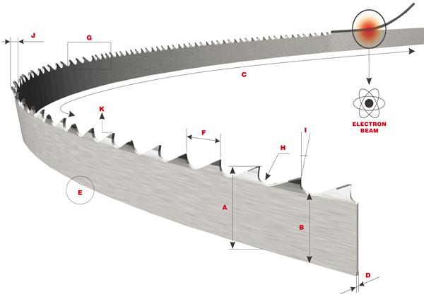
Figure 1
The basic specifications for a band saw blade are the width (A), as measured from the tip of the cutting edge to the back of the blade; (B) length, measuring along the back edge of the blade; (C) thickness; (D) back edge, or the opposite side of the blade from the teeth; (E) tooth pitch, the distance from the tip of one tooth to the next tip; (F) teeth per inch; (G) gullet, the curved area between two teeth; (H) tooth face, which can have a positive or straight rake angle, as measured against a line perpendicular to the back of the blade; (I) tooth set, the bending or tilting of the teeth, right and left, to create blade clearance through the cut. Illustration courtesy of The L.S. Starrett Co.
A wavy tooth set has groups of teeth set to each side of the blade by varying amounts in a controlled pattern. A wavy set is used on blades with a fine-tooth pitch for cutting thin sheets, tubes, and sections.
An alternate tooth set is a recurring sequence of teeth set alternately left and right. An alternate set can cut fast, though the surface finish might not be smooth.
Fabricators cutting structural shapes often choose a raker tooth set. The most common option for a range of cutting applications, a raker tooth set has a recurring sequence of teeth set left and right, followed by one tooth unset (or straight). The frequency of unset teeth on variable-pitch blades changes depending on the tooth configuration. The raker set usually is used to cut thick materials and provides a smooth surface finish.
When bundle cutting, the possibility of material moving while being cut can increase dramatically, depending on which material is being bundled. For instance, round material tends to spin, which leads to premature blade dulling and increased potential for teeth stripping.
To avoid this, be sure to use nesting clamps or some other means of clamping the material from all sides. While some fabricators tack weld the ends of the material to prevent spinning, this does nothing for vibration at the cut end of the material.
The second challenge is size. Blade selection is critical when cutting structurals and no less so when cutting bundles of structural materials. In a structural application, a band saw might bundle-cut different workpiece geometries at once, including both angles and solid shapes. When determining blades for this kind of bundle cutting, consider the width of solid pieces and the thickness of the structural shapes.
Consider the L shape of typical angle iron, with two arms. If a band saw cuts an angle alone, sitting vertically, the blade contacts the vertical arm first and then, near the end of the cycle, suddenly contacts and cuts the entire width of the horizontal arm. For this reason, angle that is cut alone often is oriented with legs extended downward (see Figure 3).
The right machines and blades can withstand high stresses, but the right fixturing and bundling strategy could reduce those stresses—and when it comes to stress in band saw cutting, less is best. For instance, when structural shapes are bundled it is not unusual to have a solid square or rectangular bar surrounded by several pieces of angle iron, with both arms nested snugly against the solid shape.
Most base their blade selection primarily on the solid portion of the bundle, as it represents the largest amount of steel being cut. Once again, the blade is expected to multitask as it cuts through the solid, as well as through the thickness of the arm of a single piece of angle iron.
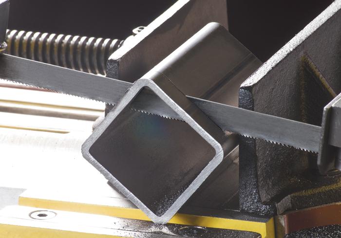
Regardless of the fixturing challenge—be it in bundle or single-piece cutting—orienting the structural piece matters. Square structural tubes, for instance, can be fixtured in a diamond orientation (see lead image) to minimize teeth engagement and reduce cutting stresses throughout the cycle.
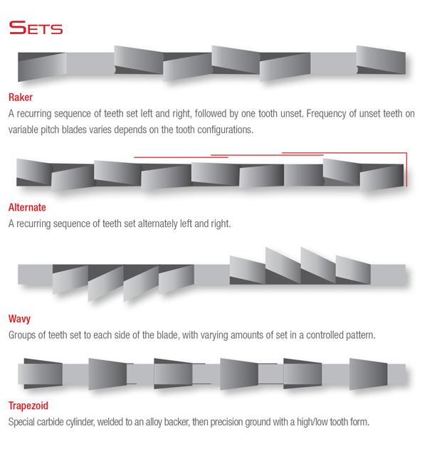
Figure 2
Tooth sets create clearance for efficient chip evacuation. This shows overhead views of various tooth sets. Illustration courtesy of The L.S. Starrett Co.
For the diamond shape, the teeth engagement is somewhat constant throughout the entire cut. If this square tube were placed flat, teeth engagement would jump immediately when cutting the flat top side, drop instantly for the side walls, then jump again for the bottom side.
Of course, adjusting the cutting angle (see Figure 4) can help reduce those dramatic changes in teeth engagement. And, again, blades and machines can be designed to handle very high stresses. But bundling or fixturing strategies that reduce cutting stresses shouldn’t be overlooked.
The greatest problem for any blade cutting structural workpieces is the constant in and out sawing movement in the material that the teeth undergo. This causes excessive shearing force on each tooth and leads to premature failure. Such high stresses in structural cutting have made bimetal blades a popular choice. As its name suggests, the bimetal blade combines two materials in one blade.
The ideal band saw blade for interrupted cutting would have optimal flexibility (toughness) and wear resistance (hardness). Tough material is flexible enough to handle the highly varying stresses of interrupted cutting, but it wears quickly. Hard material wears slowly yet isn’t flexible.
Bimetal blades combine both flexible material with wear-resistant material, effectively providing the best of both worlds. This is why bimetal blade technology has played such an important role not just in structural cutting, but in a range of interrupted cutting and other high-stress band saw applications.
A typical bimetal blade has a body made of alloy steel that provides flexibility and a fused or bonded layer of wear-resistant high-speed steel (HSS) comprising the teeth. The band saw blade industry has developed various ways to join these two very different metal alloys together. These methods have involved not only novel joining techniques, but also new options in the resulting tooth geometries.
Because every bimetal tooth has a fused or bonded joint, the heat induced during joining really matters. A joining method that creates an excessive heat-affected zone (HAZ) at the joint can create an area of stress that cannot be avoided when sawing. In some instances, the HAZ can cause the teeth to tear away from the blade during the cutting operation.
The dissimilar materials in bimetal blades are joined using processes such as laser beam welding, electron beam welding, and certain techniques that use the principles behind diffusion bonding. In the typical laser or electron beam welding setup, the flexible backing abuts a thin strip of wear-resistant material (as shown by the black strip near the Electron Beam label in Figure 1). The beam welds the joint, and the tooth geometries are subsequently cut and finished. Depending on the bimetal blade’s design, the process creates a tooth in which the tip consists of the hard, wear-resistant material while the backer has the tough, flexible material.
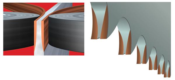
Another technique (which is patented) joins the dissimilar metals using the principles of diffusion bonding, a low-heat process. Two strips of HSS wire are joined to either side of the top edge of a backing material. After bonding, the teeth are cut. The joint geometry increases the contact area between the HSS and backing material and, hence, reduces the chance of fracture and breakage at the material interface (see Figures 5 and 6).
The resulting tooth cross section consists of three distinct regions, with two of the sections being a wear-resistant material sandwiching the backing material in the middle. This creates a stronger bond that makes it much less likely to strip teeth. The thicker tooth, together with the specific tooth geometry, limits the damage done by the interrupted cutting of structural shapes.
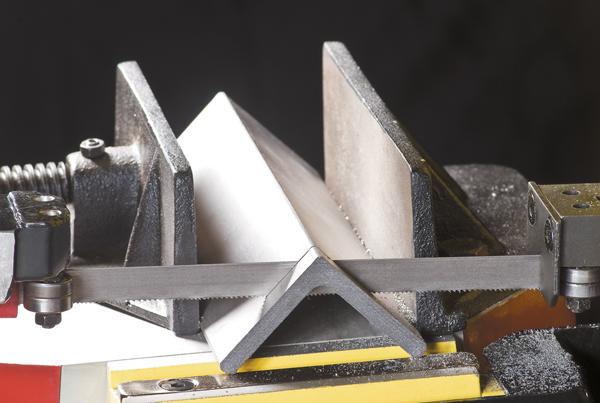
Figure 3
Angle iron is fixtured so that its arms extend downward. This minimizes teeth engagement and avoids dramatic changes in teeth engagement throughout the cutting cycle. Image courtesy of The L.S. Starrett Co.
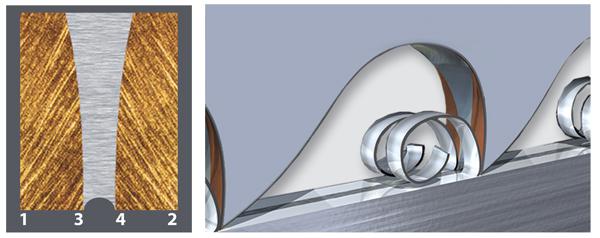
After initial use, the teeth cross section develops a U-shaped groove 0.001 to 0.002 in. deep, resulting in a unique grooved-tooth geometry. The groove remains at a constant depth and wears at the same rate as the HSS sections of the tooth cross section. This creates a blade tip with four edges of contact (see Figure 5).
The cutting action of the grooved-tooth geometry produces dual, or split, chips, each produced by the two HSS sections on either side of the backing. These chips are small and, hence, easy to evacuate (see Figure 6). The split chips are less apt to cling to the teeth because they typically curl and fall away as loose strings. Thicker chips tend to bind together in a tight mass that at some point can wreak havoc on cut quality.
The groove geometry also permits increased coolant flow to the cutting surface. Proper coolant flow will not only cool and lubricate the blade, but also flush out chips that are caught in the spaces inside tubes.
Effective sawing of structural shapes involves more than just the right blade, of course. After all, no blade will perform well if an operator doesn’t install it into the machine correctly; bundles material improperly; fails to factor in coolant type and flow; or selects improper feeds, speeds, and cut angle for the application. And, of course, carbon steel cuts very differently from aluminum and stainless, and cutting characteristics can vary from machine to machine.
Optimal sawing of structural shapes is a complicated puzzle, but understanding the capabilities of different blade geometries remains a big piece. The same goes for workpiece orientation.
Structural shape sawing puts a lot of stress on a saw blade. At the end of the day, reducing that stress makes the operation less costly and much more efficient.
Jay Gordon is North American sales manager, saws and hand tools, at L.S. Starrett.

The Fabricator is North America's leading magazine for the metal forming and fabricating industry. The magazine delivers the news, technical articles, and case histories that enable fabricators to do their jobs more efficiently. The Fabricator has served the industry since 1970.
start your free subscription
Easily access valuable industry resources now with full access to the digital edition of The Fabricator.

Easily access valuable industry resources now with full access to the digital edition of The Welder.

Easily access valuable industry resources now with full access to the digital edition of The Tube and Pipe Journal.

Easily access valuable industry resources now with full access to the digital edition of The Fabricator en Español.
In this episode of The Fabricator Podcast, Caleb Chamberlain, co-founder and CEO of OSH Cut, discusses his company’s...


