


Contributing Writer
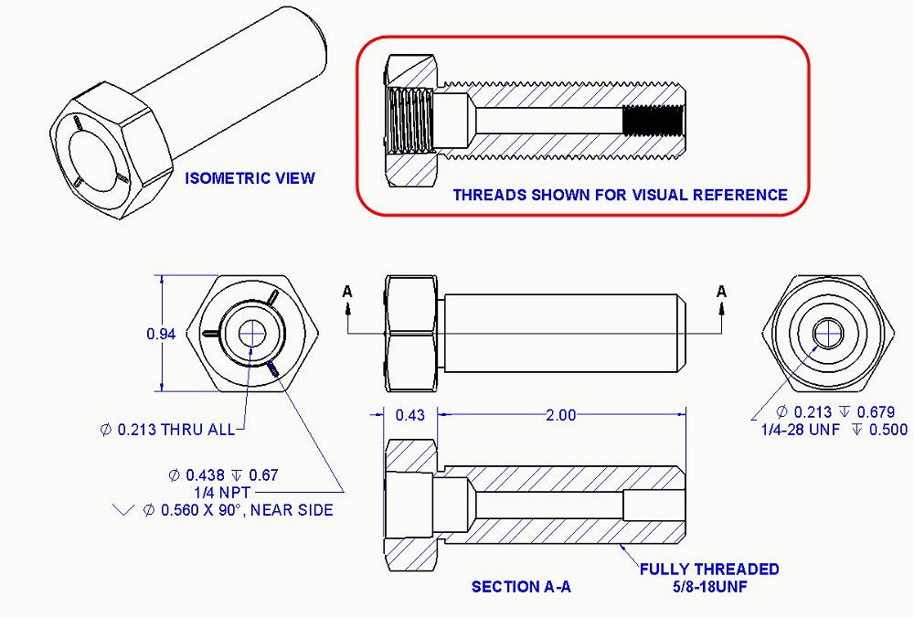
Figure 1. A 2D drawing for a modified bolt is shown. Section A-A shows the areas where thread is removed. This removal is modeled by (drum roll, please) removing the threads from the billet and attaching a hole callout—text that pretends the thread is there. The red box shows a view with threads. If perfectly modeled, such threads can be useful in fabrication.
Editor's Note: If you would like to download the 3D CAD files associated with this column, click here.
The fabrication drawing shown in Figure 1 is for a modified bolt. Starting with a common off-the-shelf item, the idea is to make a tapped hole in the threaded-end ¼-28 and to drill and tap the headed end for a ¼ NPT fitting.
Several details are revealed in the drawing. Section A-A shows our desired through-hole, a zone removed by the ¼-28 threads; a pocket made by the pilot drill for the ¼ NPT; and the tapered section removed by the pipe threads.
CAD software helps to automate the production of such drawings. The hole callouts for the tapped holes required simple mouse clicks to add the detailed drilling notes to the drawing. Such information is pulled from the modeled features in the 3D part. This helps to minimize and goof-proof the typing chore.
A CAD model that is excellent for making 2D drawings may, at the same time, be a catastrophe in fabrication. I know because I received some parts that had threadless holes that matched the STEP file (not the PDF) perfectly.
Figure 2 shows a cross-section view of the shaded 3D model that was used to create Figure 1. When it comes to tapped holes, the 3D representation of threads is a trade-off between computer speed and visual accuracy. For speed, threads are often shown as cosmetic threads – just phantom cylinders, not actual helical spirals.
The helical threads shown in Figure 3 (peek closely to see the cross section) require a few more CAD modeling steps. Helical surfaces task the computer’s video system with more work. An alternative modeling technique is to revolve “threads” instead of sweeping the helix. That illusion works great as a speed and time saver.
The scenario for this project requires that we produce both a 2D PDF (see Figure 1) and a 3D STEP file (see Figure 3).
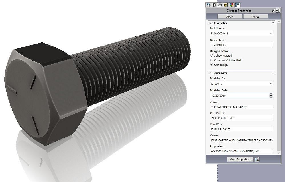
Our raw material—a common grade 5 bolt—is shown in Figure 4. To create this model, we used a revolve. Revolves take slightly fewer CPU cycles than a boss-extrude. (Sure it’s a small nuance, but we do what we can.)
The wrench flats were cut with a sketched hexagon. The forged taper on the head is modeled with a revolved cut, a small detail that adds visual credibility.
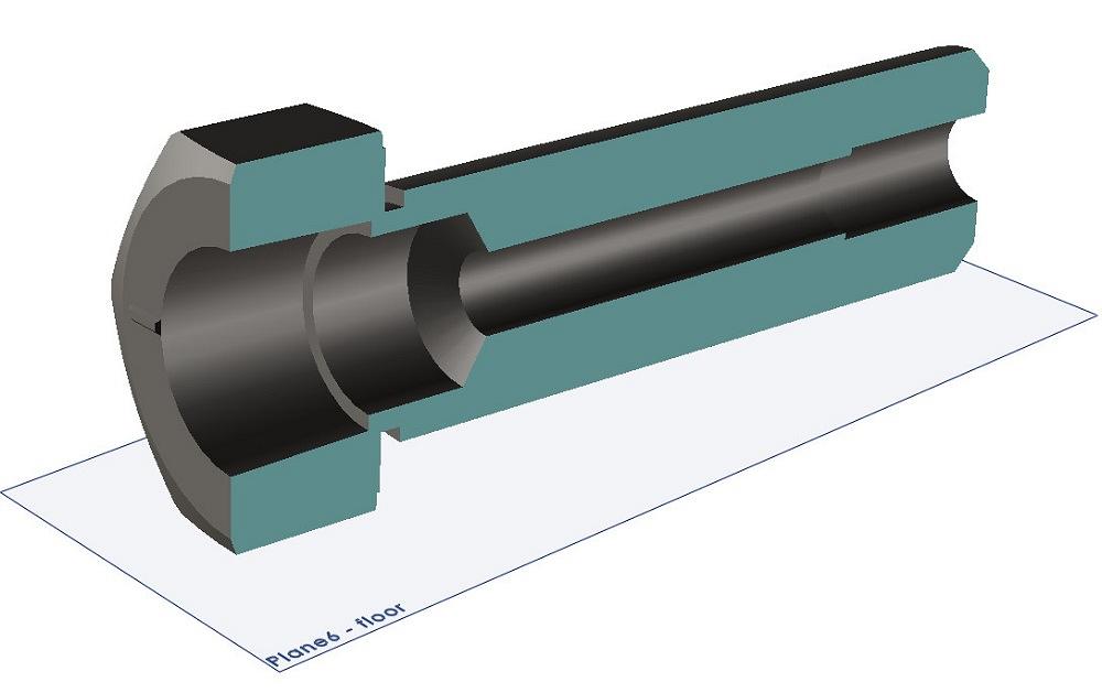
Figure 2. This is a cross-section view of the 3D model used to create Figure 1. The external threads will grow in later stages from an undersized shank. The internal threads will fill up oversized pockets.
Three bumps on the head means grade 5. The grade marking has the pattern-of-three in the sketch for a single boss-extrude. An alternative is sketching for one boss-extrude and patterning it three times, but that takes slightly more CPU effort.
The thread feature adds the 5/8-18 thread around the shank of the bolt. The thread is not needed for the 2D drawing, but it is useful for visualization. It can also be important in the STEP file that is exported for fabrication.
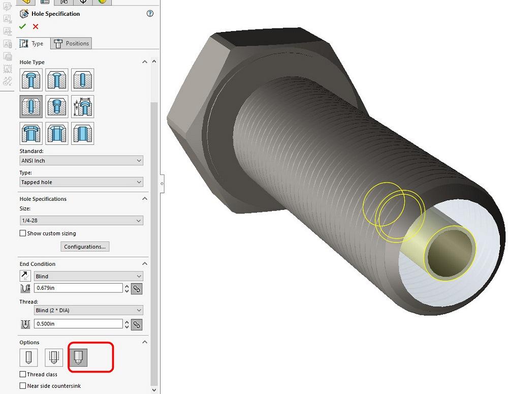
Figure 5 shows the Hole Wizard setup for drilling and tapping a ¼-28 hole. Our red box has been added to emphasize a setting—Remove Thread. This works nicely in conjunction with the Thread feature, which puts the threads back in.
For the big tapped hole, the Hole Wizard is again set to remove the threads. The missing tapered thread is modeled back in using a sweep along a tapered helix.
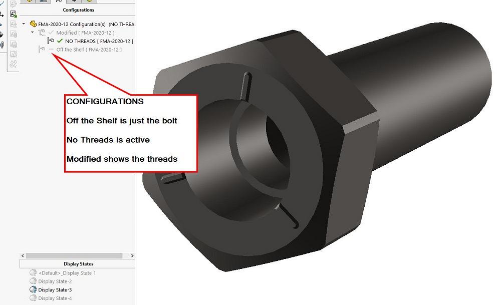
Three configurations are used to control this model. Figure 6 shows the “No Threads” configuration in the graphics window. All three of the thread features—5/8-18, ¼-28, and ¼ NPT—are suppressed in this configuration. For comparison, Figure 3 shows the model in the modified configuration.
So now we hammer home the CAD caveat: If the STEP file is going to be used for manufacturing, it is possible that the modeled configuration that works for making a 2D drawing will not work as a billet for machining. Without the threads in place, the modeled billet is too small for the external threads and too large for the internal threads.
Here’s the CAD tip: Import your export and evaluate it as a billet for machining. Are the holes too big? The pegs too small?


The Fabricator is North America's leading magazine for the metal forming and fabricating industry. The magazine delivers the news, technical articles, and case histories that enable fabricators to do their jobs more efficiently. The Fabricator has served the industry since 1970.
start your free subscription
Easily access valuable industry resources now with full access to the digital edition of The Fabricator.

Easily access valuable industry resources now with full access to the digital edition of The Welder.

Easily access valuable industry resources now with full access to the digital edition of The Tube and Pipe Journal.

Easily access valuable industry resources now with full access to the digital edition of The Fabricator en Español.
In this episode of The Fabricator Podcast, Caleb Chamberlain, co-founder and CEO of OSH Cut, discusses his company’s...


