


Senior Editor

Plenty of headaches in structural fabrication start with poor communication. If the fabricator, erector, and detailer communicate well, many headaches go away. Getty Images
Years ago David Deem worked as a project manager at a structural fabricator that did its detailing in-house. If he had a question about sequencing, connections, or any other, well, detail on the details, he’d walk over to the detailing manager’s office.
In 2013, after decades in the business, Deem launched Deem Structural Services (DSS), an erector in Longview, Texas, and periodically the staff (appropriately called the “Deem team”) meets to discuss challenges.
“And what’s the greatest challenge? It’s always communication.” Deem said this to a roomful of structural fabricators and detailers who attended NASCC: The Steel Conference, held in April in St Louis, Mo., and organized by the American Institute of Steel Construction (AISC).
A beam leaving the fab shop doesn’t have much value on its own, at least not until the steel erector does its job. So how can that beam have the most value—to make the most money for everyone involved? “It’s all about good communication,” Deem said, “and asking the right questions.”
Good communication is paramount to any business situation, especially when so many different entities collaborate to get a job done. But as Deem explained, challenging elements of the job site can cause small problems to snowball into large ones in a hurry, which can make communication problems in construction especially costly.
“It’s always good practice to get on-site to see what the erector is dealing with,” Deem said. He described a snow-covered job site at a university campus (see Figure 1). The erectors had just two days, from early Saturday morning to late Sunday afternoon, to build a pedestrian bridge. All the permitting has to be in place, as do the pieces from the fabricator, sequenced just right with connections easy to access (or at least as easy as possible) and safe to perform per OSHA requirements.
Colby Tribble, estimator at DSS, said that particular job was completed on time and on schedule. How? Because everyone was on the same page, and all drawings and other documents had exactly what the erector needed to know.
Picture a crane picking a beam between two buildings, a tight space that allows for no extra maneuvering. In this case—and it’s a very common case, especially in cities—the structural beams needed to be delivered in just the right sequence at just the right times. This calls for close collaboration among the detailer, erector, and fabricator (see Figure 2).
Collaboration can’t happen if all parties aren’t at the table. Say a fabricator and detailer move ahead on a multibuilding project before an erector is chosen. The detailer starts detailing. When the erector is finally chosen, it’s told it has to start with Building A. But it’s abundantly clear from looking at the drawings and the job site that it would be so much easier to start with Building B. But the ball’s already rolling, and the erector makes do, though expenses and delays keep mounting.
Good communication could have avoided all these headaches, and much of it could have been covered during the site-specific erection and safety plan.
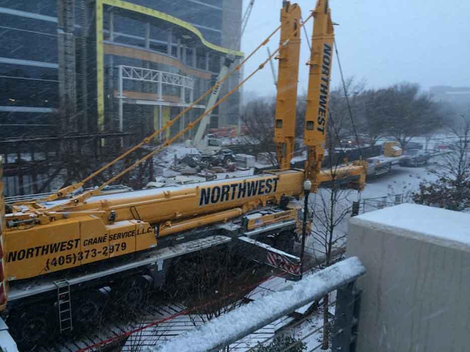
Figure 1
This pedestrian footbridge was completed on time and on schedule, despite the weather. Good communication played a big role.
“We love to have the detailers involved when possible,” Deem said. “Regardless, though, there are things detailers can ask fabricators from the get-go. These involve the sequence and schedule, as well as shipping requirements.”
Say a detailer sees a girder in the plans that’s 100 feet long, but the site won’t allow for a 100-ft. girder, be it because of space constraints, limited crane capacity, or a combination of both. “If that’s the case, what splices do we need? Where are they? Are they bolted or welded? Is there value engineering involved? Will it be shop welded or field welded? These are all things that, as erectors, if we’re invited to the party, we’ll be glad to discuss,” Deem said.
Just one missing beam can add entire days to the project schedule, sometimes more. Cranes need to be at the right spot for a particular pick. Weights on trusses need to be added and removed in just the right sequence for structural stability during erection. “In many cases, all the material has to be there in the right place, with the crane in the right spot, or it’s just not going to get erected,” Deem said. “These kinds of tight restraints are very common.”
“You now have a lot of connection design responsibility being delegated to fabricators, who then delegate it to the detailer,” Deem said. “And in many ways, that’s a good thing, because the erector can communicate directly with the detailer to achieve connections that are safe, more efficient, and work better for everybody.”
Deem called these “erector-friendly” connections— those that are safe, easy to perform, and abide by OSHA requirements. If a worker needs to climb a high ladder just to access a connection, there’s a good chance the connection is not erector-friendly.
Erector aids help, and from the steel erector’s perspective, there can never be too many. Tribble referred to a picture of an L-shape plate welded onto the end of a hollow structural section (see Figure 3).
“We call them glad hands,” Deem said, adding that these temporary aids are designed so that the connection can have the necessary support during the erection sequence.
On multistory structures, specific column-splice locations also can make the erector’s job easier. Deem emphasized that practices might vary depending on the job and erector, but DSS prefers column splices to be about 4 ft. from the top of steel (deck plate), spaced in such a way so that the erector can erect two floors at a time. With the first floor installed, the erector would work upward, installing girders and deck plate for the second and third stories, with a column splice 4 ft. above the third-story deck plate. The next column splice would be two stories up from there, 4 ft. above the fifth-story deck plate, and so on. This column-splice sequence allows erectors to work in two-story “batches.” Place those splices farther apart, and the erector needs to strategize how to pick, manipulate, and place interior beams between those tall columns.
Some structures, like three-story buildings, might specify single tall columns with no splices at all. It’s not ideal, Deem said, and it does require some upfront discussion, particularly if exterior columns make it impossible to place interior beams. The key again is communication.
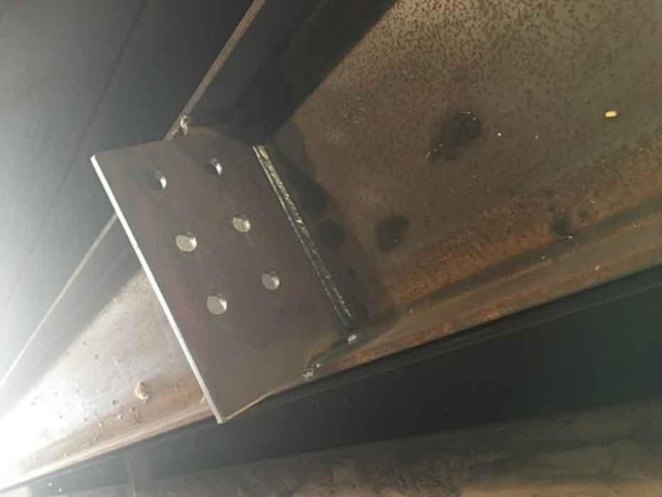
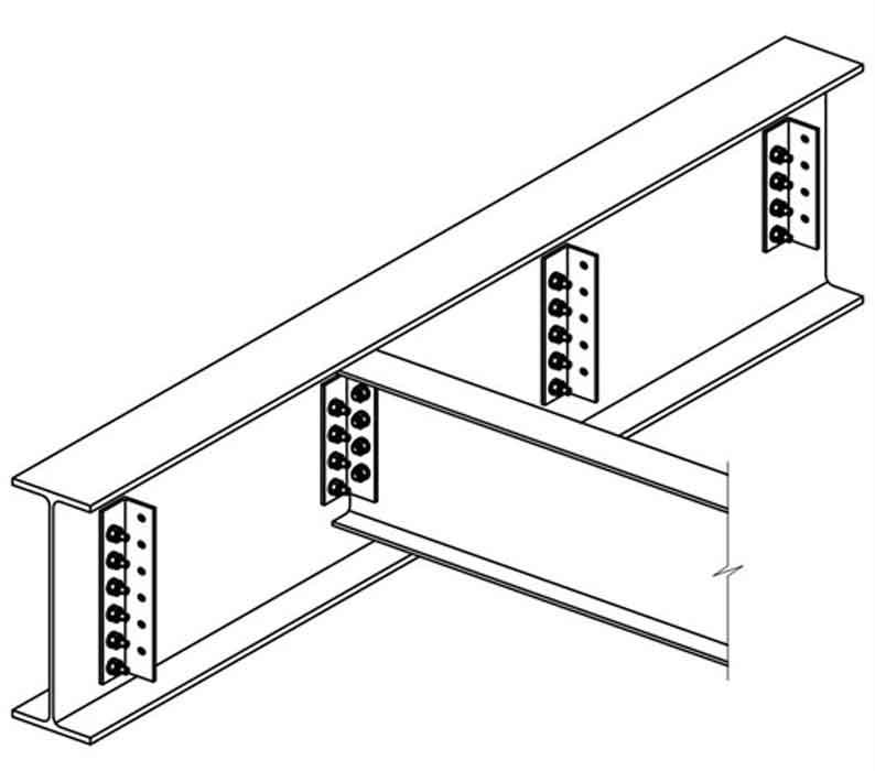
For almost two decades OSHA regulations have not allowed double connections at columns and beam webs—that is, two connections sharing connection holes—without certain erector aids (see Figure 4). Bolts do need to be staggered, so that no one bolt needs to support all three members. But the staggered arrangement still needs those erection aids. These can be an angle seat (welded angle iron support) or connection flange with a notch that allows space for at least one bolt from the opposite member to remain in place as the second member is bolted in place. Without these, the erector needs to have a welded seat or a member to support the load during the double-connection process. Fabricating these on-site isn’t ideal, of course, with a massive crane on-site and a schedule to keep.
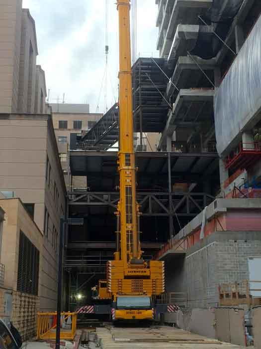
Figure 2
The space for this crane leaves little room for error.
If beam connections share the same hole pattern, yet only one beam has an angle seat at the connection, the drawings should specify on which side of that connection to start, per the sequence. Or, to errorproof the process, a fabricator can simply place an angle seat on both sides, so that no matter the sequence, the connections go together as they should, safely and per OSHA requirements.
OSHA also requires erectors to use perimeter safety cables before erecting the next tier, and those cables need to go through holes or otherwise be securely attached to the perimeter columns. In fact, OSHA uses the phrase “shall not”—that is, an erector shall not erect without those cables. “When you see ‘shall not’ in OSHA regulations, that doesn’t mean ‘Well, it’d be a good idea.’ It means you shall not,” Deem said. “So if a fabricator sends me a perimeter column without holes or tabs to run our cables through, OSHA says I’m not allowed to stand that column until I do something about it.”
When Deem and his team review drawings, they look for what they call the “erector-friendly column.” Specifics vary depending on the job, but in many cases the ideal column has four anchor bolts or rods; holes at the top of columns for a shackle or a pull pin; holes for perimeter cables; plenty of double-connection aids; perhaps even a few tie-line holes for a fall-arrest system; bolted joist seats; and, not least, some extended shear tabs to allow easy connecting, including the bolting and torqueing that’s needed at moment connections (see Figure 5).
The right shear tabs can make an erector’s job much easier, faster, and safer—and it’s a key erector aid that can be discussed, especially if connection design has been delegated to the fabricator. With representatives from the erector, detailer, and fabricator sitting at the table, the three can discuss if and where shear tabs make sense. With everyone on the same page, the fabricator then can write a request for information (RFI) to get those shear tabs approved.
Deem conceded that extended shear tabs do require welding. “A lot of fabricators will tell us, ‘We don’t want to do shear tabs. We’ve got to weld that. We want to just run this through the beam line.’ And I get that.”
In these cases, Deem has proposed a shear-tab alternative, if the loads will allow (see Figure 6). “It’s essentially a shear-tab connection that’s a bolted angle clip. Those angles are bolted in the shop. Then when it comes to me, it’s essentially a shear tab.”
Another common issue comes with bracing connections, with HSS or similar member connecting at a 45-degree (or nonperpendicular) angle to a base member. It’s common for those bracing connections to have just one hole. That means the erector must partially bolt and then use tools to ensure everything is properly aligned before tightening the connection. In these cases, two or more bolt holes make an erector’s job much easier.
“Aligning with just one hole can be done,” Deem said, “but it’s a heck of a lot easier to have one hole for alignment and another hole for securing the bolt.”
“Our favorite connection is a bolted bracing,” Tribble said, with sufficient number and correct placement to properly align during erection and take the load. “This eliminates the welding, which saves everybody time, money, and headache.”
The more field welding and cutting a project takes, the more complex and expensive it becomes—usually (but not always, as described later). Angles for deck support columns are a prime example. Deem described deck support columns with 3- by 3-in. angles. Many times a fabricator will simply send the angles for the erector to field-cut.
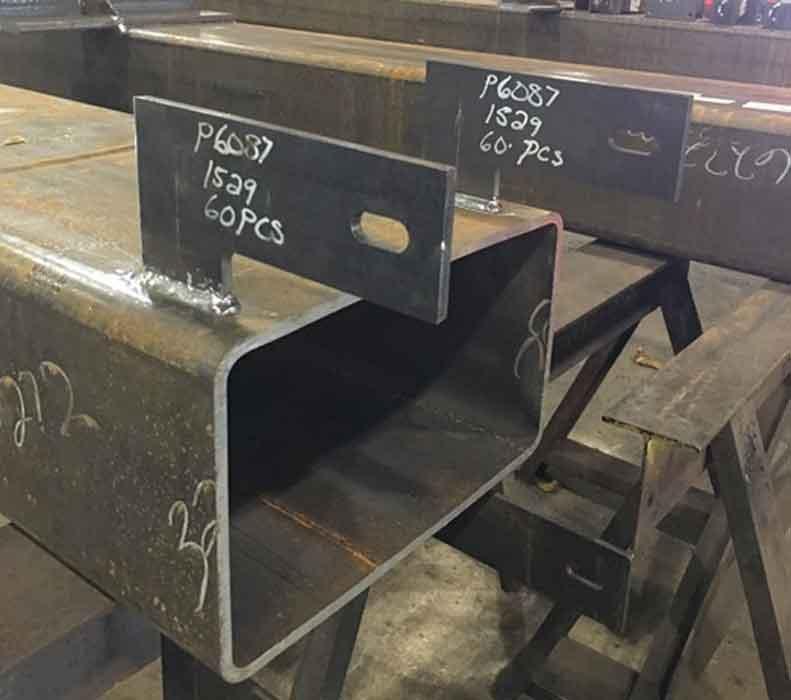
Figure 3
These temporary erector aids, sometimes called glad hands, can make the erector’s job much easier.
As Deem explained, “Truth of the matter is, no matter what the beam sizes are, if you can come up with an angle that’s coped, we can make that angle fit nearly all the situations we’ll encounter on that building.” He added that field cutting in particular can be problematic, because on many job sites, no one can fire up a gas cutting torch without approval from the engineer of record.
Of course, doing more fabrication in the shop doesn’t always make erection easier. Tribble described situations in which stiffener plates are welded to the web where two other beams connect. A fabricator might think it’s helping by welding stiffeners to both sides of the beam in the shops, but on-site the beam with both stiffeners simply doesn’t fit. So the erector has no choice but to cut the plate out and field-fabricate during erection. With the right communication with the erector, the detailer and fabricator would have known to leave one stiffener plate off, to be welded in the field.
Deem pointed to a weld-all-around symbol on a drawing and shook his head. “That’s every erector’s favorite weld symbol,” he said sarcastically.
“Is that what you really mean? Sometimes you can’t even weld all the way around. And we know we probably don’t need to weld it all the way around. This is where we need detailers, through the RFI process, to ask the question.”
Why ask? Welding costs money. A continuous weld costs more than a stitch weld. Overhead welding costs even more money. Tough-to-access full-penetration welds can cost even more.
Field welding issues often crop up as a project makes its way through bidding and final approvals. Deem described several instances in which an erector’s initial bid assumed connections would be bolted. Then as the contract documents made their way through approvals, the engineer increased the loads, which in turn required more full-pen welds, some of which were placed not far away from some easy-to-access fillet welds. Are those fillet welds sufficient to take the loads? They might be sufficient, or they might not. But if the erector is involved in the discussion (again, as early as possible), the question at least is being asked.
“It’s about communication,” Deem said. “We can ask those questions proactively during the approval process.”
One question that’s often missed: Is the building in a seismic zone? Many engineers, especially those who design buildings in seismic areas, end up detailing the joining as if it were a seismic-zone project, even though it’s not—like removing a backing bar and having a weld’s root pass backgouged and inspected.
“If we’re not in a seismic zone, maybe I do not need to take the backing bar off,” Deem said. “Maybe I don’t have to backgouge. And if they do want me to backgouge and weld it, maybe I don’t even need the backing bar.” He emphasized that requirements vary depending on the job and situation; the key is simply asking the questions.
Imagine a situation in which the detailer contacts the general contractor and asks about a dimension for an elevator shaft in the middle of a building. He doesn’t get an answer, so to protect himself, he puts the connecting beam on hold. Of course, that hold halts the entire erection sequence—all for a few W10x12 beams. “So now I’m out there with a huge crane, and I can’t hang any of the building, all because of these little W10s,” Deem said. “But if we’re proactive, we can keep things on schedule.”
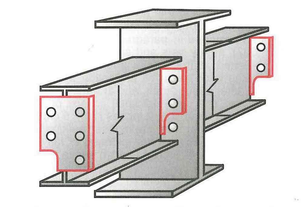
Figure 4
Per OSHA, a double connection needs some type of erector aid, like a notch that allows at least one bolt of the first member, on the opposite side of the central member, to remain in place.
Specifically, the erector can field-fabricate to the dimensions when they’re available. In the meantime, erection can continue on schedule. Yes, this might increase field fabrication costs slightly, but it’s nothing compared to the days lost while beams are on hold as an RFI remains unanswered.
Tribble emphasized that field fabricating might or might not work, depending on the job. But if there’s a way to avoid a costly hold, the idea at least should be presented.
“I can get paid for work I did,” Deem said. “But anyone will tell you that it’s extremely difficult to get paid for work you didn’t do.” When a project is on hold, it can be extremely difficult to get paid for those lost hours.
Of course, today’s software can track beams from the time they’re drawn to the time they arrive on-site, so these holdups should theoretically be a rarity. Software can flag problems far ahead of time and see multiple sequences into the future. But things happen and beams sometimes don’t arrive when they’re needed. As Deem and Tribble explained, this is why no level of software can replace good communication practices.
It really all boils down to time. If detailers give erectors drawings that spell out the sequence and connections, and they’re on sturdy paper that can withstand the elements, a raising-gang foreman’s day will go a lot smoother, and he’ll accomplish a lot more in less time.
“We’re in the digital age, and we do use tablets for shop drawings,” Deem said. “But I can tell you that most raising-gang foremen are going to use paper for the erection drawings.”
Those drawings show splice locations, clear as day, and their locations should be a result of a consensus among the detailer, fabricator, and erector. When consensus is reached, procedures are followed, everyone is on the same page, and erection then can go into high gear.
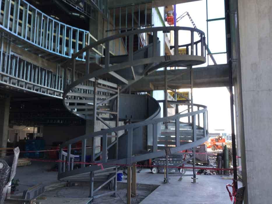
Tribble described a project involving a spiral staircase encased in glass (see Figure 7). The project looked incredibly daunting. But in this case, the fabricator, detailer, and erector had met, discussed all the details, and, lo and behold, installation went faster than expected.
“The general contractor was worried it would take weeks,” Tribble said. “But when all was said and done, we installed a rolled spiral stair, from start to finish, in three days. The better the detail, the quicker the fabrication goes up, the more money everybody makes, and everybody’s happier.”


The Fabricator is North America's leading magazine for the metal forming and fabricating industry. The magazine delivers the news, technical articles, and case histories that enable fabricators to do their jobs more efficiently. The Fabricator has served the industry since 1970.
start your free subscription
Easily access valuable industry resources now with full access to the digital edition of The Fabricator.

Easily access valuable industry resources now with full access to the digital edition of The Welder.

Easily access valuable industry resources now with full access to the digital edition of The Tube and Pipe Journal.

Easily access valuable industry resources now with full access to the digital edition of The Fabricator en Español.
In this episode of The Fabricator Podcast, Caleb Chamberlain, co-founder and CEO of OSH Cut, discusses his company’s...


