


Contributing Writer
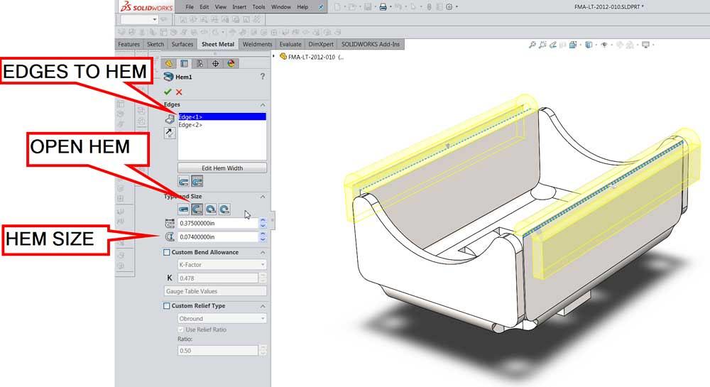
Figure 1a
This is a CAD setup for an open hem on two edges. Note that closed hems, teardrop, and edge bead are all available from this control panel.
A reader recently asked for guidance in using 3-D CAD for sheet metal parts. We continue the theme from last month: Skilled designers know how the sheet metal parts get bent.
The recommended CAD work flow is to design with size and function of the end product as the modeling intent. A concluding step in the work flow is to derive the flat workpiece from the finished product’s manufacturing information.
As an alternative CAD work flow, model the flat workpiece first and then add bends to create the final shape. While that would resemble the fabrication process, such a CAD work flow—where the conclusion is presented and an argument is to follow—is not recommended.
A hem is a single, 180-degree bend. Some hems are closed—basically a zero inside bend radius. If the hem has a radius greater than zero, it resembles a U in cross section. Unlike the U-channels discussed in Part III, the hem has only one bend instead of two. If no flat section to the hem is evident, it is simply an edge bead.
In 3-D CAD a hem is very easy to create. As shown in Figure 1a, pick an edge or edges, set a depth, and decide on the gap. The CAD hem’s angle can be adjusted past 180 degrees to create a closed teardrop or underbent to create an open hook. To bead an edge, simply select that hem type in the hem feature’s setup. The model with hemmed edges is shown in Figure 1b.
As a design element, the hem creates the appearance of greater thickness without adding much weight. It creates a very smooth edge and can hide the raw edge of the part. This is sometimes a way to add durability to painted parts. Hems can be useful as a way to stiffen a sheet metal panel.
Hems have drawbacks, however. With plated steel parts, the interior of the hem can be very difficult to cover for corrosion control. This can be a serious problem because the inside of the hem is easy to wet but challenging to dry.
In the fab shop, the hem is created with multiple bending strokes or machine cycles. Machine cycles take time, and as a result, hems add expense to the design. As additional expense, the hem requires a unique tooling setup separate from that for 90-degree bends.
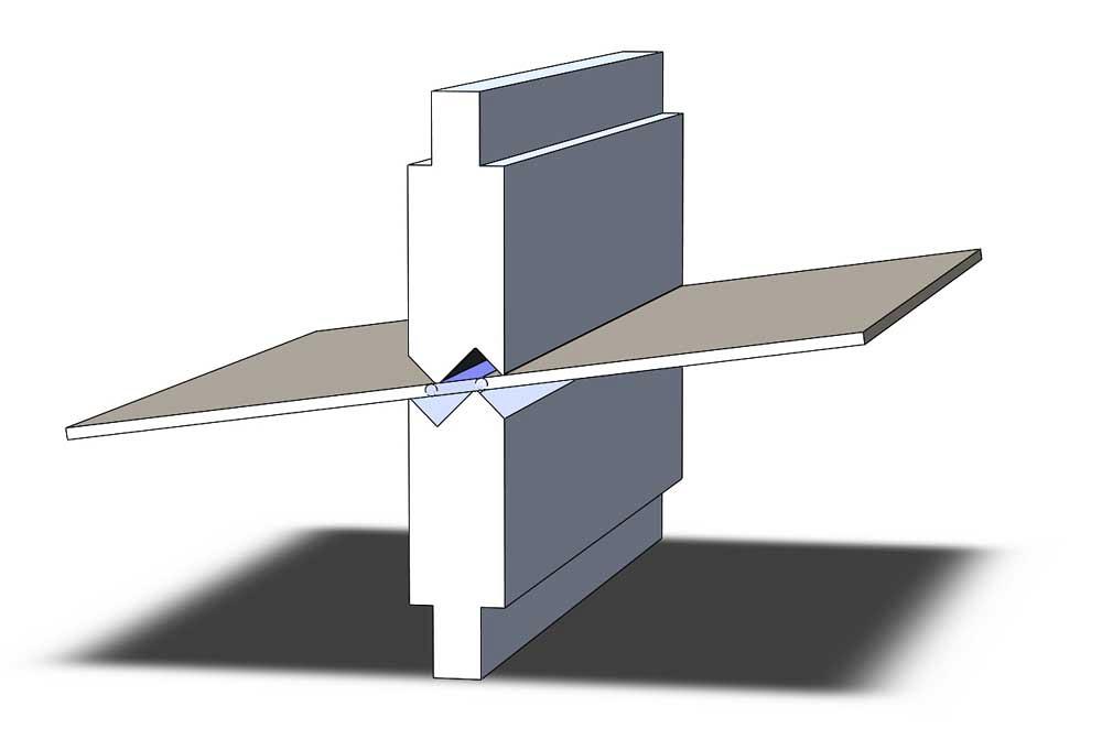
Figure 2a shows the flat part positioned, ready for the first bend. The first bend in creating a hem is an acute angle bend, something greater than 120 degrees to define where the center of the hem bend will be.
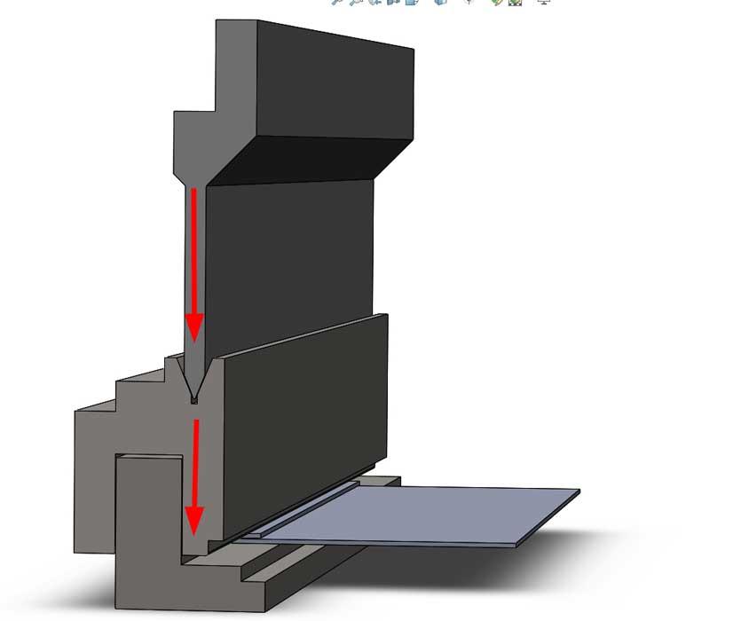
As the top punch descends to contact the workpiece, the spring-loaded die set is compressed (see Figure 2b).
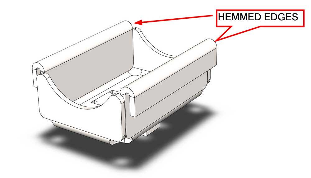
Figure 1b
The completed hem is shown. Note that the perfect arc for the inside radius may be difficult to fabricate. It probably will be more parabolic than a true radius.
The initial acute bend in a hemming operation is often completed rather slowly as the workpiece flops and whips during the initial forming cycle. Even a moderately sized workpiece may require a pair of brake operators to support the whip of the workpiece. Extra labor is another reason that hems are such expensive features when compared to simple 90-degree bends.
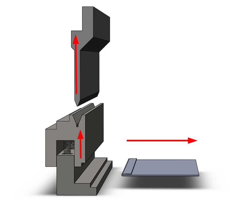
As the press brake completes this first stroke, the top punch is raised, and the die set springs lift to their normal position. At that moment, the workpiece is released.
The workpiece is then positioned for the final bend (see Figure 2c). This is a spanking operation made with flat faces in the die set. The top punch is lowered into the empty V die and continues down to compress the springs in the die set. The spanking operation deforms the acute starting bend into the final 180-degree angle (see Figure 2d). Note that the radius on an open hem bend is usually deformed because of this spanking operation.
Once again, as the press brake completes this final stroke, the top punch is raised, and the die set springs lift to their normal position. The hemmed workpiece is then released (see Figure 2e).
Such tooling is time-efficient relative to setup with general-purpose tooling, but the hemming die set is limited to a specific hem size.
Here’s a CAD tip: Avoid unnecessary tooling expense. Check with the fab shop to learn the sizes and features of hem tooling that is already on hand.
A jog bend is simply a pair of equal and opposite bends closely spaced to create a lazy Z offset, which is often equal to the material thickness. This makes for a nice fit and finish with a mating cover, perhaps. The jog bend also does a nice job of stiffening an edge without adding much bulk or thickness.
As with the hem bend, a jog bend is easier to model than it is to fabricate. A jog bend requires specific tooling, setup, and machine operation that are distinctly different from that used for creating 90-degree bends.
Here’s a DFM tip: Jog bends carry their own nonrecurring engineering costs and setup requirements into the overall production costs. Yep. It’s the same as hems.
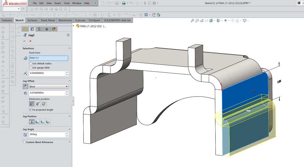
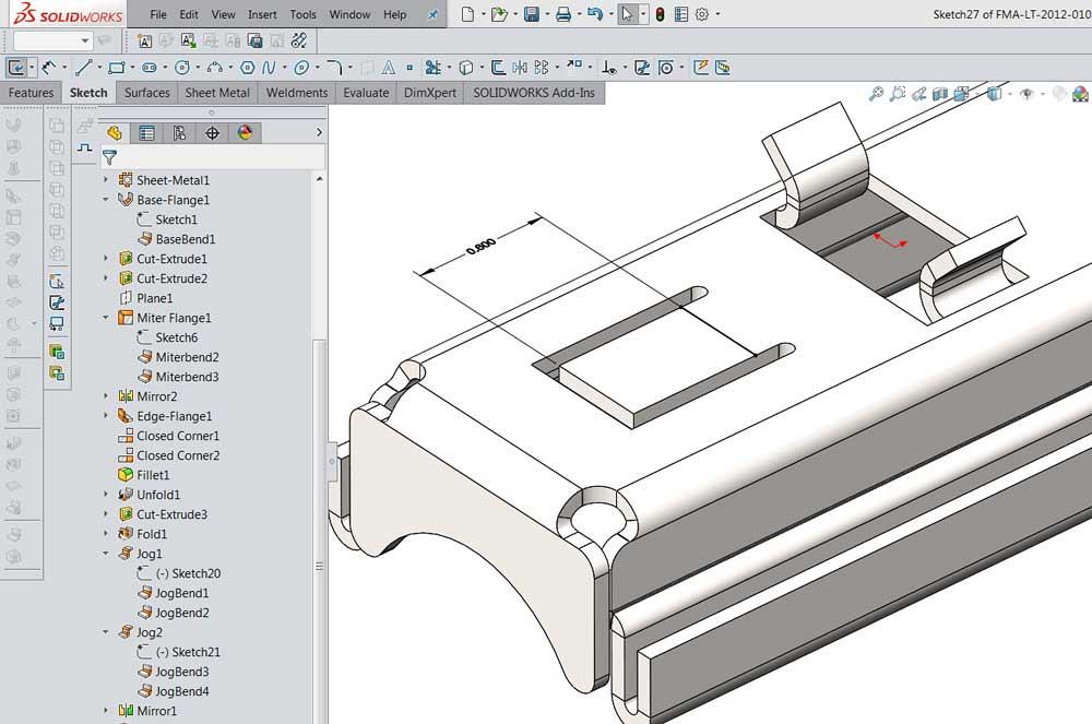
As shown in Figure 3a, the jog bend is set up in 3-D CAD by sketching a line to locate the bend, setting the surface offset distance, picking a bend radius, and choosing an angle for the pair of bends.
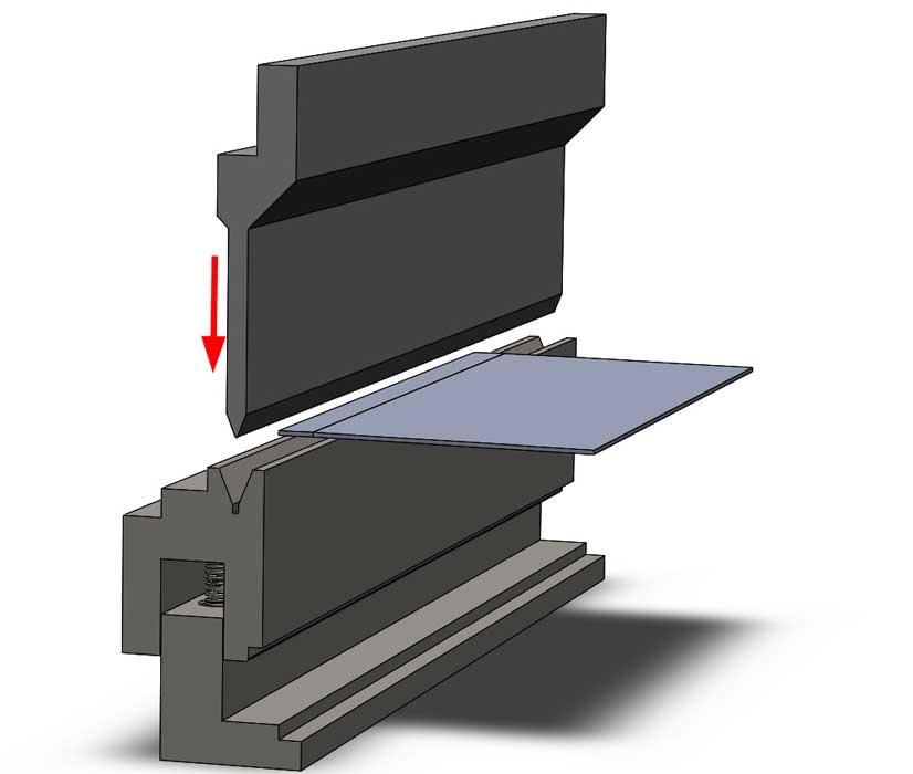
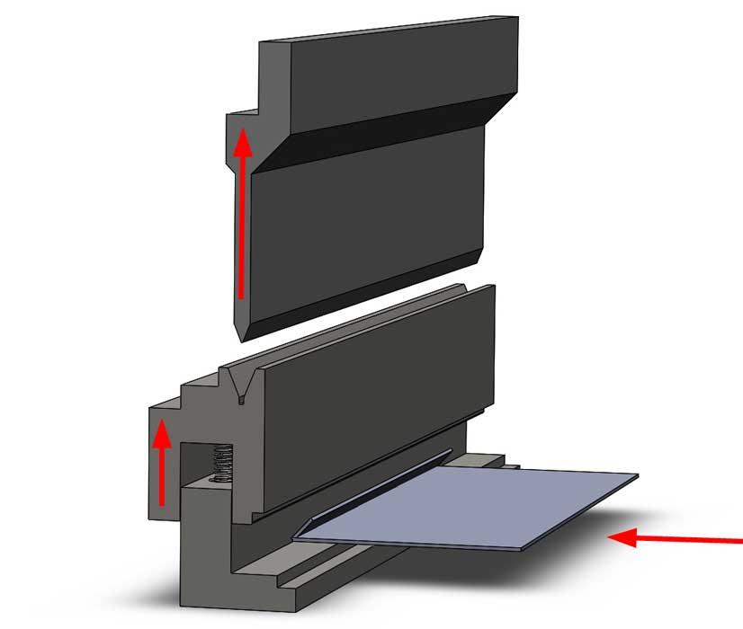
Figure 2a
Figure 2a
This model represents the function of a “Dutch bend” hemming die set. The brake operator positions the workpiece over the V die. The upper tool descends under press brake power to contact the workpiece.
Here’s another DFM tip: To match the actual behavior of jog tooling, override the bend radius on the Jog feature and set it to a small value, 0.004 in., for example. Also override the bend angle and set it to a value less than 90 degrees. A jog’s internal angle at 80 degrees is generally a good starting point. The model with jog bends is shown in Figure 3b.
In the fab shop, the jog bend is created with a die set that presses both bends into the workpiece simultaneously (see Figure 3c). Not surprisingly, a jog bend takes about twice as much pressure to create as a single bend does.
The jog bend is typically completed as a bottom-bending operation. That is to say, the tooling does not coin, but it does fully contact the workpiece. If the jog tooling is being bottomed, then set the internal jog angle closer to 90 degrees instead of the recommended 80 degrees (see Figure 3d).
Jog bending results in slightly different stretching of the workpiece than two simple 90-degree bends. Consult with the fab shop for its experience with calculating flat layouts around hems and jogs. Adjust the jog radius and angle to match actual tooling.
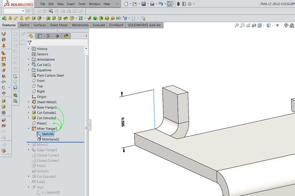
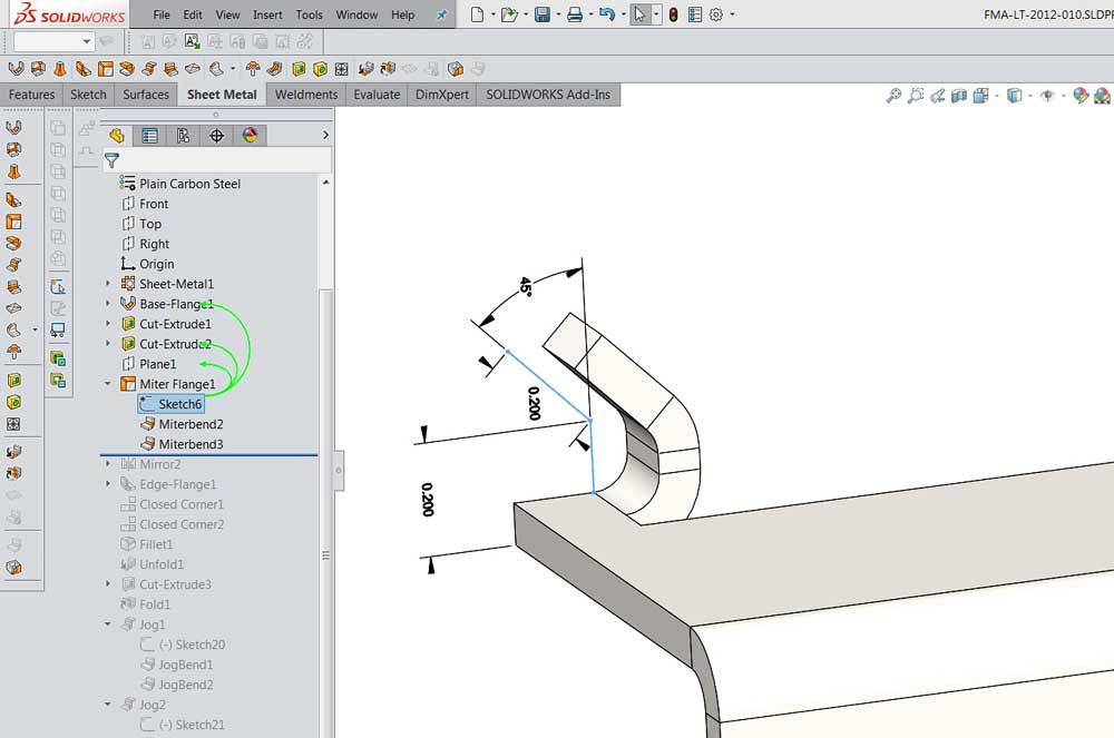
In the CAD shop, a miter flange is a time-saving miracle. A simple sketch can create one (see Figure 4a) or more bends (see Figure 4b) on one or more edges in a single modeling step. When more than one edge is selected for routing the sketch for the flange, the resulting corner is mitered at 45 degrees to create the needed flat layout.
Here’s a DFM tip: When setting up a miter flange, remember that bends will be overbent to allow for springback; include at least a 0.015-in. gap in mitered corners.
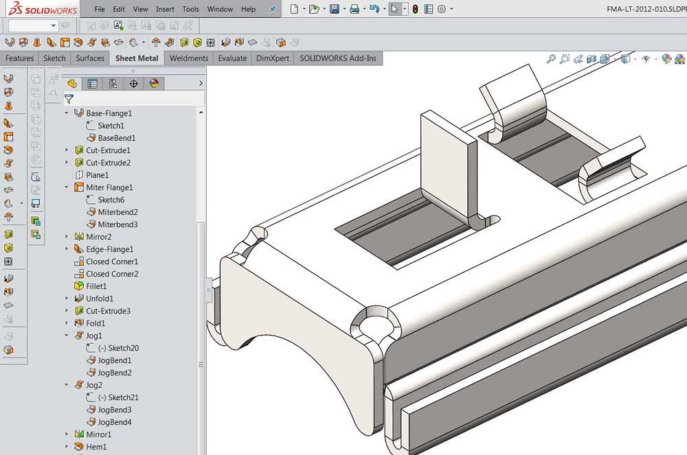
The Sketched Bend feature is very similar to the Jog feature except that only one bend is created (see Figure 5a). As with the Jog feature, a single line sketch locates the bend.
The result of this example sketch is shown in Figure 5b.
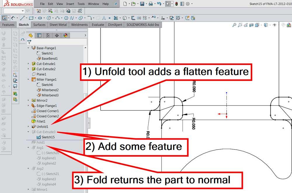
It is sometimes advantageous to model features in the flat workpiece rather than in the formed product. The CAD tools Unfold and Fold provide a parameter-driven design feature to unfold any or all bends in the model.
Figure 6a shows work-in-progress for adding bend relief cuts in the corners of the flat part. The CAD work flow is:
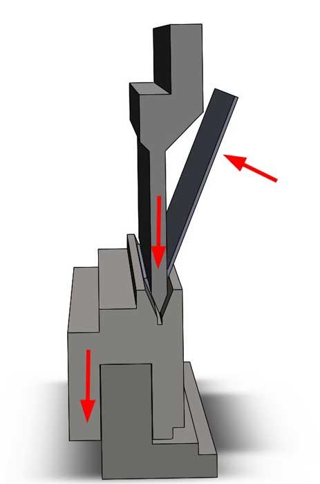
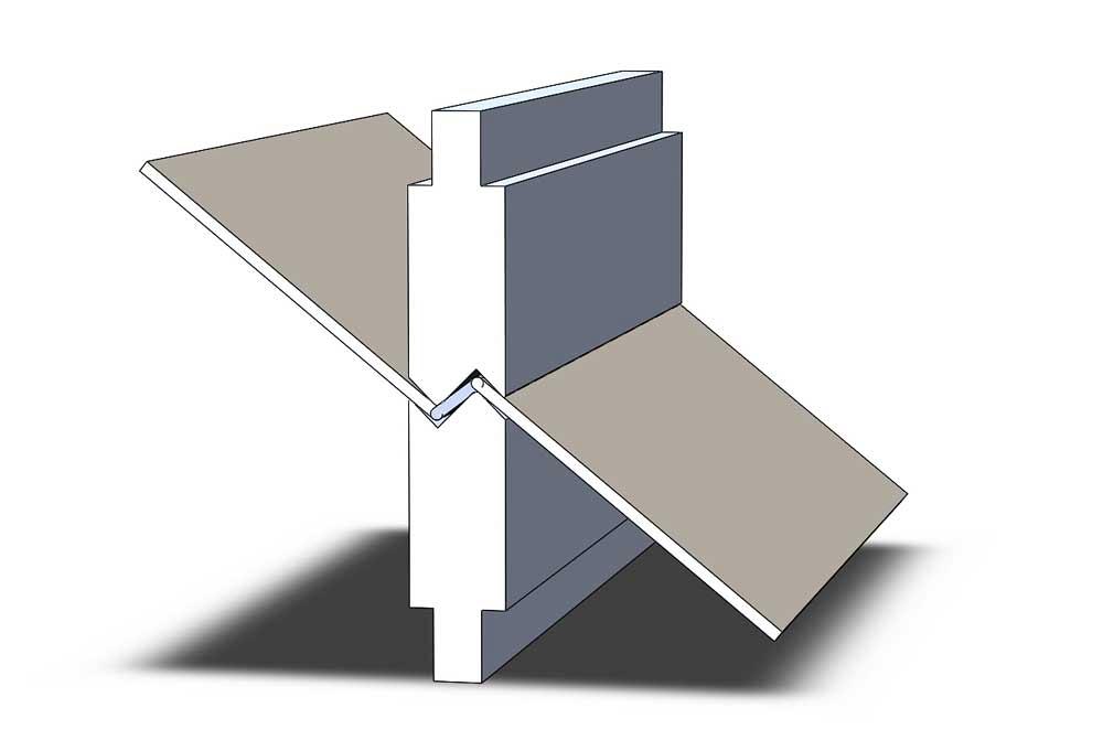
Figure 2b
An acute bend is formed in the workpiece as the upper tool is lowered. The pressure from the upper tool compresses springs in the lower die set.
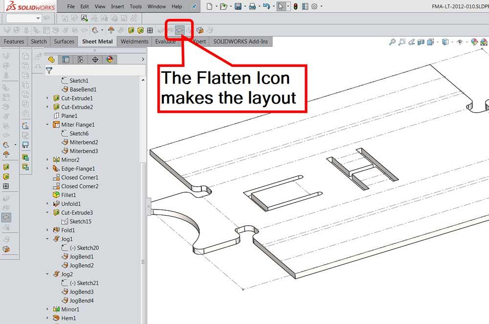
Similar in result to the Unfold tool, the Flatten icon (see Figure 6b) toggles the model between flat layout or the default, which is the formed configuration. This toggle icon is a convenient way to switch between folded and flat.
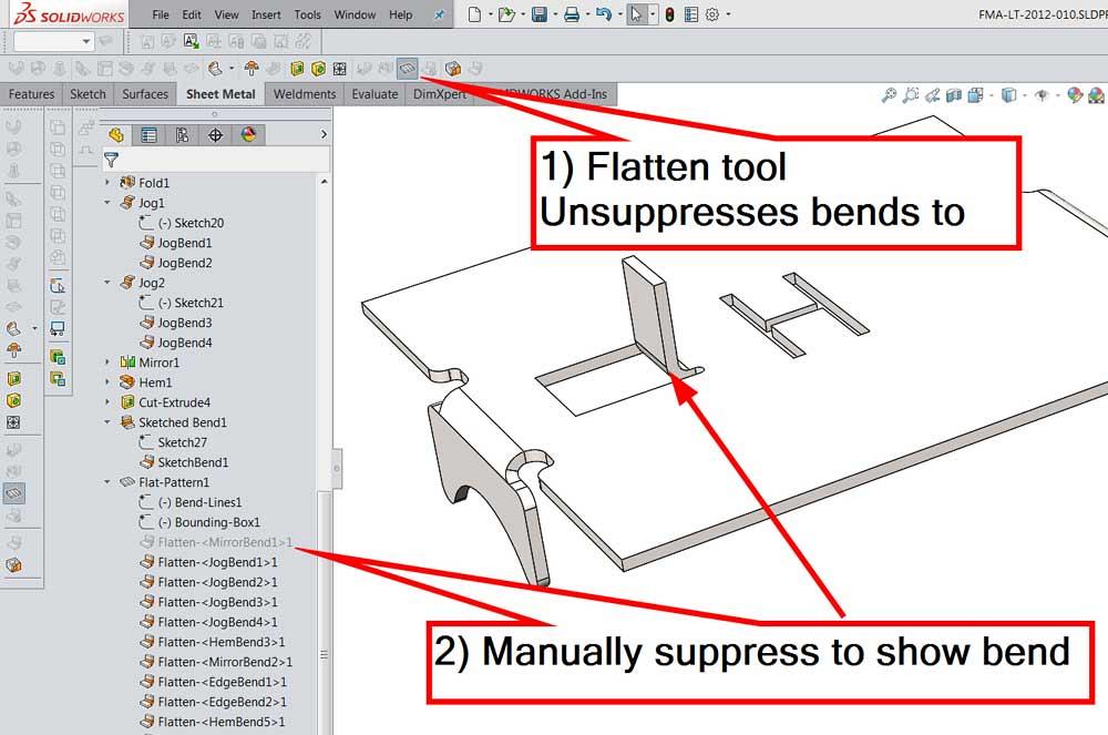
The CAD jockey can take advantage of the way the Flatten icon works to create step-by-step folding instructions. As each bend is processed in CAD, that bend is flattened. If the bend processing for that bend is suppressed, then the bend is not flattened. Figure 6c illustrates the trick. The first step is to unsuppress all bend processing to get a flat layout. A quick way to do that is to click on the Flatten icon.
Next, suppress the bend processing for a desired bend. To do that, select the bend, right-mouse-click, and select Suppress. The bend appears. In Figure 6 almost all of the bends are processing, or in the flat state.
By adding configurations to the model, we can create quick transitions between flat and folded in a specific sequence. This bend processing trick might come in handy for designing illustrations for origami manuals.
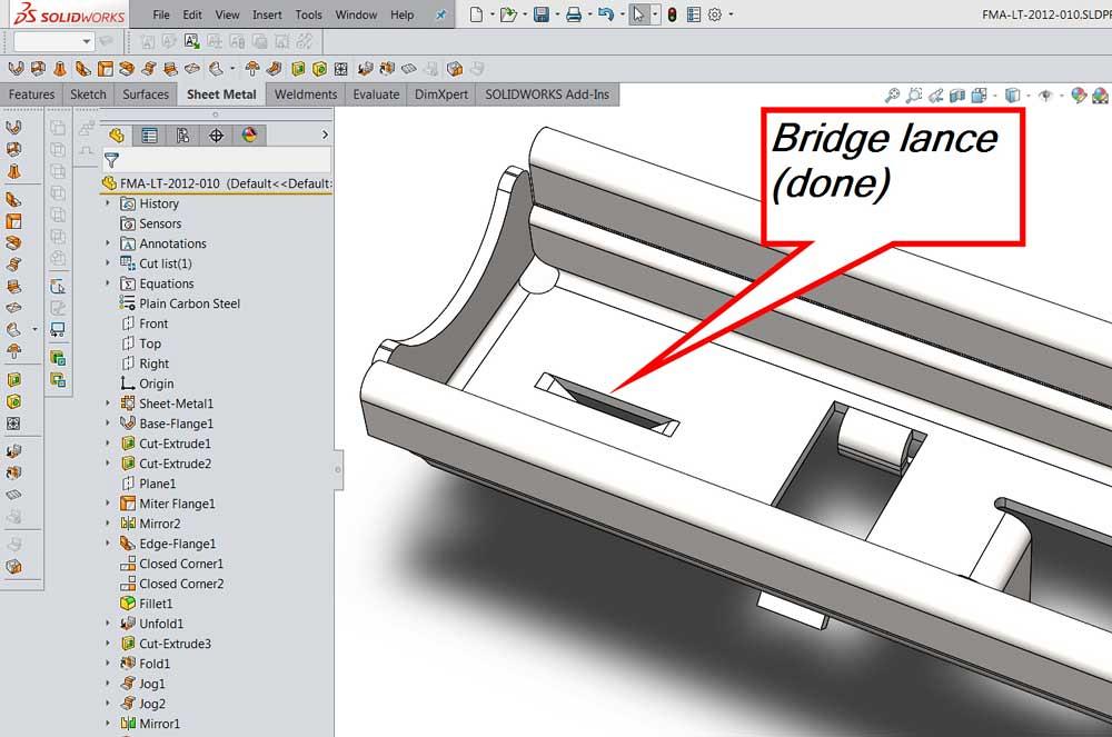
In the fab shop, punching machines use dedicated tooling for applications such as stamping extruded holes, forming louvers, lifting bridge lances, and embossing countersinks. In the CAD world, these stamped and formed features can be tedious to model. To keep the tedium to a one-time occurrence, a CAD jockey can use a Forming Tool, a CAD analog for the actual tooling die set.
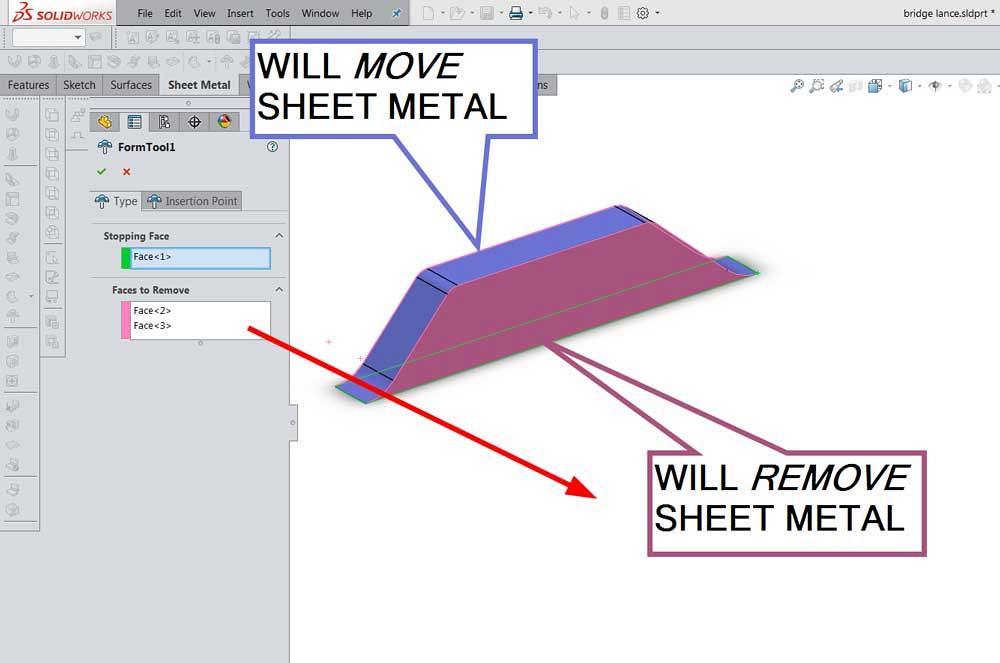
The Forming Tool model is separate from the workpiece model being designed. An example for a bridge lance tool is shown in Figure 7a. The Forming Tool model represents the interior of the feature being embossed—very much like the male punch in the actual die set. While creating the Forming Tool model, the CAD jockey defines a stopping face. Additionally, cut (instead of stretch) can be specified to create openings; the sides of the bridge lance are open, for example.
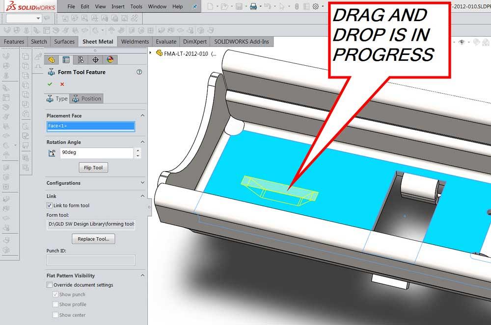
As represented in Figure 7b, the Forming Tool model is drag-dropped from its folder onto a face of the sheet metal part. The Forming Tool model may be located and rotated for precise positioning. The result of applying this bridge lance forming tool is shown in Figure 7c.
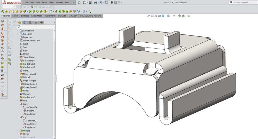
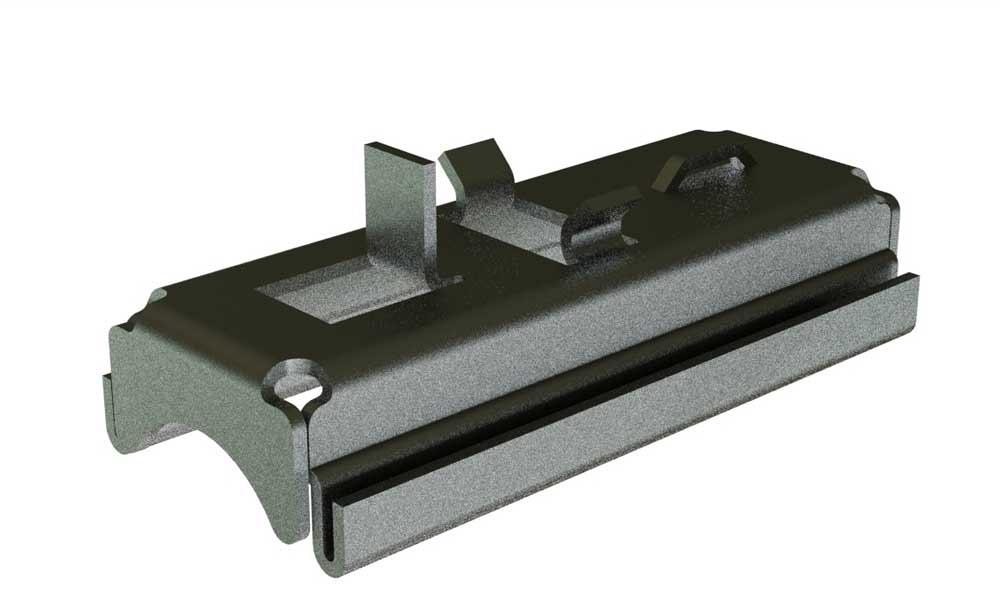
The design shown in Figure 8 has evolved into something that requires several setups. It was easy to model and will be easy to edit, though.
Gerald Davis uses CAD software to design and develop products for his clients at www.glddesigns.com. From 1984 to 2004 he owned and operated a job shop.
Gerald would love for you to send him your comments and questions. You are not alone, and the problems you face often are shared by others. Please send your questions and comments to dand@thefabricator.com.


The Fabricator is North America's leading magazine for the metal forming and fabricating industry. The magazine delivers the news, technical articles, and case histories that enable fabricators to do their jobs more efficiently. The Fabricator has served the industry since 1970.
start your free subscription
Easily access valuable industry resources now with full access to the digital edition of The Fabricator.

Easily access valuable industry resources now with full access to the digital edition of The Welder.

Easily access valuable industry resources now with full access to the digital edition of The Tube and Pipe Journal.

Easily access valuable industry resources now with full access to the digital edition of The Fabricator en Español.
In this episode of The Fabricator Podcast, Caleb Chamberlain, co-founder and CEO of OSH Cut, discusses his company’s...


