


Contributing Writer
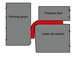
Figure 1
Part II of this series presented a basic overview of metal forming operations, such as bending, flanging, drawing, ironing, coining, curling, hemming, and embossing. This and future installments discuss these operations in more detail. We will look at factors controlling the success of each operation, as well as tooling design guidelines. Let's begin with metal bending, a process oftenperceived as the simplest.
Bending can be defined simply as a forming operation in which the metal is deformed along a straight axis. Both compression and tension occur when bending sheet metal. The inside radius of the bent metal is in compression, or being squeezed together. The outside bend radius is in tension, or being stretched.
Because of the metal's elastic properties, it wants to decompress on the inside radius and return to its flat shape on the outside radius (Figure 1), which causes springback. Also know as elastic recovery, springback is present in all metal bending operations.
For a 90-degree bend angle, the metal must be bent to an acute angle (less than 90 degrees) and allowed to spring back to its finished position, a difficult task given the fact that a press ram typically travels vertically only. In addition, because of natural mechanical variability in the material from coil to coil and from the beginning of the coil to its end, attempting to achieve aconsistent, precision angularity in a bending operation can be very difficult.
If ultraprecision bend angles are required, one of the best things you can do to achieve them is to design the tool so that it can be adjusted quickly, safely, and effectively to compensate for incoming variables.; Changing the product design also can help reduce springback and inconsistency problems. Incorporating darts, ribs, or gussets into the part design will enhance stiffness and reducethe amount of springback (Figure 2).
Several basic types of bending methods can be incorporated into a stamping operation—wipe bending, V bending, and rotary bending. All three are popular, and each has its advantages and disadvantages.
Wipe Bending. One of the most common methods used, but not always the most effective, is simple wipe bending. Unfortunately, this method does not allow for much overbending other than the very slight acute angle that can be achieved by wiping the side extremely tight (Figure 3). Even though wipe bending effectively creates a bend, controlling the bend angle isvery difficult. This method is not well-suited to bending high-strength metals or for parts requiring precision bend angle tolerances. Wipe bending can be improved by capturing the outside profile of the radius with the forming die section.
Figure 4shows a coin relief method. This process allows the outside radius to be coined, or squeezed, near the lower tangent point, which causes under- or over -bending to take place. The coin relief method works best when the metal is bent over a radius that is equal to or less than one metal thickness, and the metal is not ultrahigh-strength. One advantage to this method isthat by vertically shimming the forming section up and down, the gap, as well as the amount of coining, can be adjusted. This allows for easy adjustments to be made for variability in the metal's thickness and mechanical properties.
Figure 5shows a pivot-style bending method, which incorporates both wipe bending and cam motion. This design works well both to create the bend and to adjust the amount of overbend. Overbend is created by adjusting the lower driver block vertically up and down.
V Bending. A very good method for obtaining a given bend angle, V bending is undoubtedly the most common method used with press brake bending. An acute angle ground on both the punch and die can provide adequate overbending of the metal. Also, the bending amount can be altered by adjusting the amount of coining the metal undergoes at the bottom of the press stroke(Figure 6).
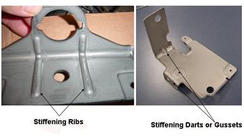
Figure 2 Photos courtesy of Batesville Tool and Die Company.
One disadvantage to V bending is that it often requires the part to be rotated in such a manner that sometimes is difficult to incorporate in a progressive die. An advantage is that it often requires less force to create the bend compared with conventional wipe bending.
Editor's Note:
Part I provides an introduction to stamping.
Part II covers various forming operations.
Part III discusses several production methods used to make stamped parts.
Part IV and Part V cover common stamping die components.
Part VI explains specialty die components.
Part VII provides an overview of metals used in stamping, and Part VIII continues this discussion.
Part IX covers the mechanical properties as well as behavioral characteristics of metals.
Part X begins an in-depth look at the metal cutting process.
Part XI defines slug pulling and common causes.
Part XII describes methods for resolving slug-pulling problems.
Part XIII discusses various specialty metal cutting methods used in stamping operations.
Part XIV explains fineblanking and GRIPflow®.
Part XV describes several bending methods—wipe, coin relief, pivot, and V bending.
Part XVI continues the discussion of bending in stamping operations, focusing on rotary and reverse U bending. It also addresses the advantages and disadvantages of rotary bending.
Part XVII discusses the fundamentals of drawing and stretching.


The Fabricator is North America's leading magazine for the metal forming and fabricating industry. The magazine delivers the news, technical articles, and case histories that enable fabricators to do their jobs more efficiently. The Fabricator has served the industry since 1970.
start your free subscription
Easily access valuable industry resources now with full access to the digital edition of The Fabricator.

Easily access valuable industry resources now with full access to the digital edition of The Welder.

Easily access valuable industry resources now with full access to the digital edition of The Tube and Pipe Journal.

Easily access valuable industry resources now with full access to the digital edition of The Fabricator en Español.
In this episode of The Fabricator Podcast, Caleb Chamberlain, co-founder and CEO of OSH Cut, discusses his company’s...


