


Senior Editor
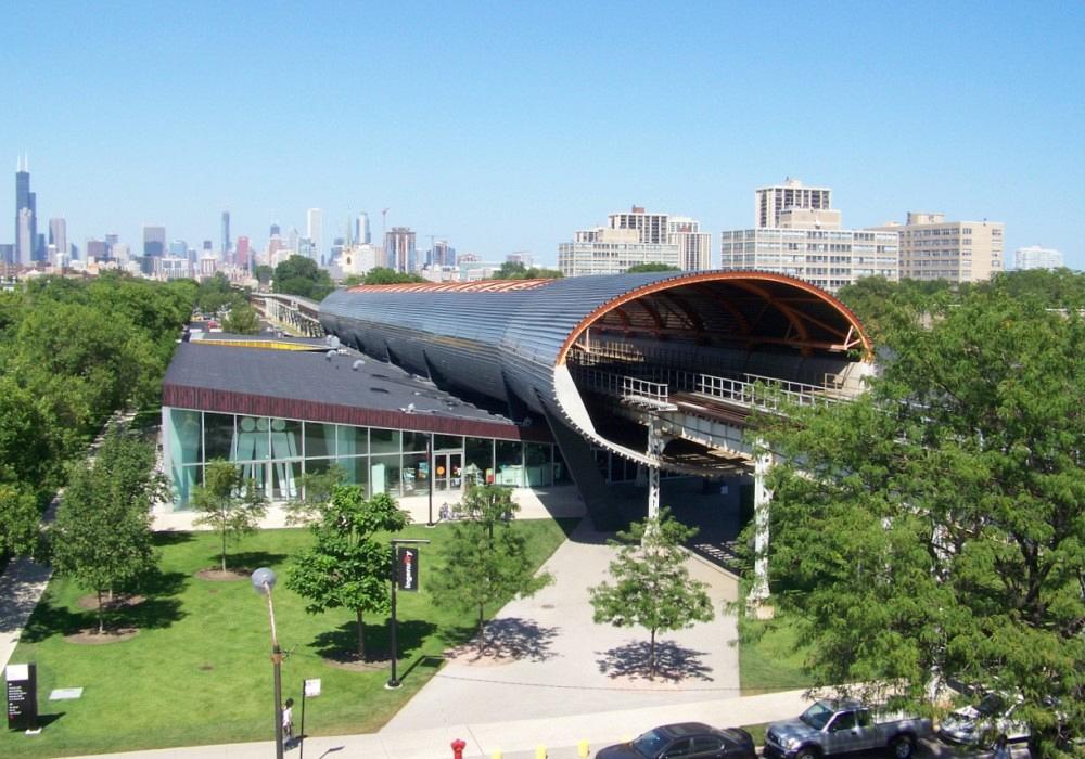
Students studying at Illinois Institute of Technology enjoy the quiet. An elliptical tube, consisting of numerous curved members, muffles the sound of passing trains. Image: AISC
Whenever Ken Pecho strolls through the campus of his alma mater, Illinois Institute of Technology (IIT) near downtown, he looks up. When a CTA train navigates the rail, he enjoys the quiet. Sure, the train isn’t silent, but it’s much quieter than it would otherwise be thanks to an elliptical tube acting as a kind of muffler, formed at Pecho’s employer, Chicago Metal Rolled Products (CMRP), a bender-roller that has been forming plate, angle, tube, profiles, and structural beams for more than 100 years. Surrounding the CTA tracks, that elliptical structure, consisting of numerous curved members, dampens the noise of passing trains, much to the relief of IIT students studying in a building just several feet away.
Pecho recalled this story during a presentation at the 2019 NASCC Steel Conference, held in St Louis and organized by the American Institute of Steel Construction (AISC). During a presentation at the conference, he held what was then a new AISC publication, “Design Guide 33: Curved Member Design.”
“This really should be considered the curved member bible,” he said. “If you fabricate curved metals in your daily schedule, this is something you should have in your library.”
The design guide dives deep into Pecho’s presentation topic, one that has become increasingly top of mind for bender-roller operations that have in recent years seen a significant demand spike for curved profiles, including round, elliptical, square, and rectangular tubes; open profiles; and structural beams. Pecho’s talk covered distortion.
“The No. 1 concern we see with curved metals is distortion,” he said. “But we can’t eliminate distortion completely. It’s just not possible. So, now the question becomes, how do we design for bending? What can we do to aid the successful outcome of a curved member?”
The most successful projects, including that curved elliptical tube surrounding the CTA train tracks, were designed with distortion in mind. Pecho recalled a job in which one rectangular curved tube was joined to a straight rectangular tube, a situation where distortion issues would be readily apparent, especially considering the curved tube’s tight radius.
The rectangular tube’s shape would shift only slightly, so on its own the workpiece’s distorted shape wouldn’t be noticeable. But this wasn’t the case for the welder who would be mating the curved and straight workpieces together. The solution involved a compromise: The shop bent the profile, but then left several feet of an unbent straight section near the end of the tube. The fabricator then cut that tube back to a few inches ahead of the curve, just enough space for the distortion effects in the curve section to dissipate, returning the tube diameter to its nominal dimension.
Luckily, in this situation, the connection—hidden behind a wall—wasn’t cosmetically critical. If it were, designers might have had to reconsider the connection type or design. Again, on its own, the curved workpiece’s distortion wasn’t noticeable. But joined to a straight member, the distortion effects were apparent. Such cosmetic faults might not matter. Regardless, acknowledging and planning for that distortion on the front end, before any metal is bent, can make a world of sense.
The new AISC guide does specify how different levels of distortion affect a member’s strength. To calculate certain strength attributes of a curved I-beam, for instance, divide the out-of-flatness delta (difference from nominal) that the distortion creates by the material thickness. Results up to a certain point show no meaningful change in the member’s strength; but as the distortion grows beyond that point, the member does weaken. Localized distortion can be especially problematic. All these calculations hinge on the application’s strength requirements, of course, and the AISC design guide spells out all the specifics.
Most distortion problems do not stem from structural integrity or strength. As Pecho explained, quality bender-roller operations would never dream of sending out a curved section so weakened from distortion as to create a safety hazard. But problems do arise when it comes to cosmetics which is of particular importance in architecturally exposed structural steel (AESS) and similar work, as well as connection requirements.
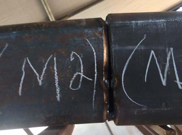
FIGURE 2 This connection shows the effect of shrinkage on steel members. The rectangular tube on the left was curved to a tight radius and, hence, underwent slight shrinkage of the tubes cross section in the plane of bending. The shrinkage isn’t noticeable to the naked eye—until it’s mated to a straight section.
A curved tube mating to a straight tube will not have the same edge profile (see Figure 2). This might or might not be a big deal, depending on the connection method and cosmetic requirements. But if the designer wants a circumferential weld with complete joint penetration, member fit-up really matters. Sometimes fabricators use hydraulic jacks on the inside diameter to push it open slightly so it can mate with a straight tube. It’s doable but time-consuming, costly, and perhaps entirely unnecessary if the job were engineered with distortion in mind.
A metal workpiece’s lattice structure has what’s known as slip planes that interact when forming. “When under constant yield,” Pecho explained, “metal tends to take on almost fluidlike characteristics.”
When a tube, beam, or open section bends, compression builds on the inside radius and tension builds on the outside. Left uncontrolled, especially on thin-walled workpieces, these forces create localized distortion like wrinkling or buckling on the inside radius, wall thinning and shrinkage on the outside radius, and distortion and ovality of the overall profile shape.
A square tube can morph into a trapezoid, with excessive growth on the inside-radius dimension accompanied by shrinkage on the outside radius and to the cross-sectional profile in the plane of bending. Rectangular tubes, left unsupported during bending, might become concave, especially on the inside radius wall. The web and flanges of structural beams can ripple.
The experienced profile bender recognizes the almost fluid nature of material during bending. In a sense, compression and tension forces metal when under constant yield to “flow” in certain ways and to certain unconstrained areas. Consider the bending of a rectangular tube. If the tension forces pulling against the outside wall generate excessive stretching, that wall can shrink, which in turn affects how metal “flows” or moves elsewhere. The metal growth and shrinkage takes the path of least resistance. And in an unsupported situation, due to the counteracting forces of compression and tension, this path might be toward the member’s neutral axis and often offset to the inside of the bend; hence, the outside wall also can become concave. These tension forces, combined with compression on the inside radius, cause the inside wall dimension to grow. Left with no place to go, the metal on the inside wall buckles and, again, becomes concave (see Figure 3).
As Pecho explained, the rectangular tube is just one among many shapes profile benders must “read” when setting up and operating a machine. They must predict what areas of the workpiece will grow, what will shrink, and set up the machine, tools, and procedure to accommodate for each. Again, the goal isn’t to eliminate distortion. Instead, operators aim to control how tension and compression forces act upon a workpiece, through machine and tooling selection and movements throughout the bending operation, to control where the growth and shrinkage occur. It’s all done in a way that doesn’t affect the finished product’s design intent and strength requirements.
Bender-rollers form profiles either with hot bending or cold bending. Hot bending includes induction bending, which applies a narrow band of heat to a profile as a bending arm pivots to make (usually) a very tight-radius bend.
Cold bending, as the name suggests, bends the workpiece in a cold state. On occasion, cold bending of large profiles occurs in a rotary draw machine. Once primarily used only by tube fabricators that focused on relatively small-diameter work, some large rotary draw machines can bend workpieces 10, 15, even 17 in. in diameter. CMRP, for instance, has a rotary draw machine for tubes and pipes up to 10 in. dia. That said, these machines require extensive tooling, including wiper dies (which mitigate wrinkling on the inside radius), bending dies, and sometimes internal mandrels, all of which do not come cheap.
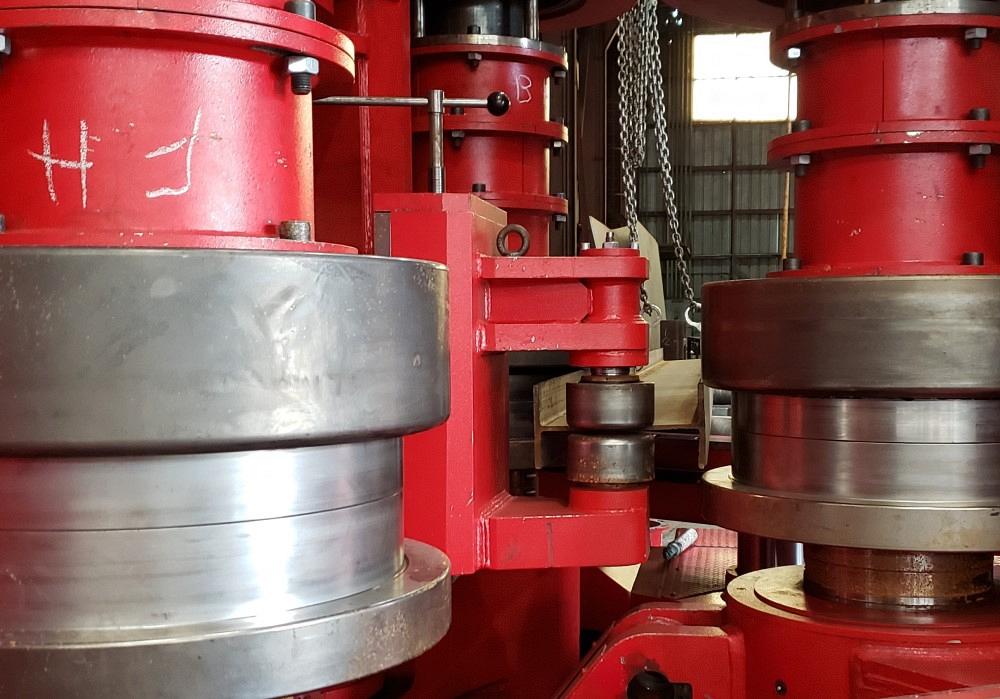
The three-roll bender is the industry workhorse. The machine has three hydraulically driven rolls in a triangular configuration. In a typical horizontal configuration, viewed from overhead, material is fed between the two top rolls and single bottom roll until the end of the material touches the far roll. The distance between the middle of the far roll and the middle of the bottom roll is called the grip length (see Figure 4), which provides leverage to induce the force needed to create the bending moment. The greater the grip length, the more leverage you have. The downside: In most cases, the material within that grip length needs to be scrapped, which is the reason most bender-rollers request material that is a little longer than what’s required.
A 20-in.-dia. tube might require a 4-ft. grip length on each end, though, as Pecho explained, grip lengths depend on myriad factors, including machine type, setup, and tooling. But generally speaking, the smaller the workpiece diameter, the less grip length it requires. Setup considerations also change with the workpiece orientation, that is, whether it’s being bent on its longer strong axis, the hard way, or along its shorter weak axis, the easy way.
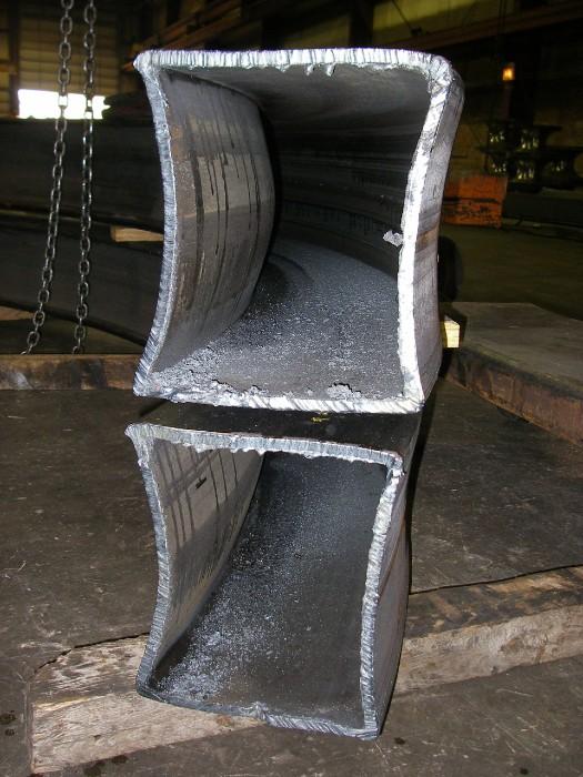
FIGURE 3 In this extreme example, uncontrolled growth and shrinkage led to noticeable concavity on the inside and outside walls.
Operators aim to bend the workpiece in as few passes as possible. To that end, they choose one of two approaches: asymmetrical or symmetrical bending. Symmetrical bending occurs when the operator uses all three rolls to induce bending force as he passes the workpiece forward and backward through the three-roll pyramid setup. Ideally, asymmetrical bending occurs in just one pass as the operator relies on the far top and single bottom roll (hence the term “asymmetrical”) to induce the bending force. Operators might need to work the material through another pass, especially if they’re working with an unusual or challenging job; but if they do, the bending is usually extremely slight.
Symmetrical bending takes more time, but as Pecho explained, it’s a much “safer” process, often performed by operators with less experience. Still, operators can’t perform too many passes or they’ll risk overworking the material. All that work hardening changes how the material shrinks and grows and often leaves the workpiece with unacceptable levels of cross-sectional distortion.
For tubular profiles, symmetrical bending also limits the kind of internal support operators can insert into the workpiece. They can still pack sand in the ID, one of the oldest techniques still in use to mitigate distortion. Or they might rely on other creative methods. Pecho described several instances in which operators bent a tall, thin rectangular tube to a very tight radius by inserting several smaller-diameter tubes inside it. Of course, those internal tubes can’t be removed after bending; they’re stuck inside there forever. As long as the increased weight is acceptable, they shouldn’t negatively affect the workpiece’s design requirements.
Mandrels can’t be used on a second pass, lest they become lodged forever inside the workpiece, which is one reason (other than the increased productivity) that experienced operators perform asymmetrical bending. Similar to the mandrels used in rotary draw bending, they’re used in three-roll profile bending to support the workpiece ID as the bending moment is applied, minimizing dimples, dents, concavity, or other signs of uncontrolled distortion.
The chance of uncontrolled distortion rises any time the radius changes. This, of course, includes the initial moment when a radius is first induced. The initial pressure from tooling induces localized forces, especially in asymmetric bending or in other setups where the operator needs to bend a profile in as few passes as possible to avoid overworking and outright material failure.
Insufficient grip length can make the problem worse. “If we have insufficient grip length, you’ll see a dent in the location where the bottom roll initially touched the material,” Pecho said. “But, if you provide enough grip length, you can then cut the member back into the ‘good arc,’ beyond the dent, so the dent won’t be present in the final workpiece.”
Extra stress can occur again in workpieces with compound radii, especially if the radius “steps down” sequentially to tighter and tighter radii. “During every stepdown, you’ll generally see differences in the profile shape,” Pecho said. “The differences might be negligible. It all depends on the desired shape, the radii, and the wall thickness.”
The goal is to make all those “shape shifts” and other distortion effects negligible. The initial efforts ideally occur in the design phase, including the choice of radius (or radii) for a member, its dimensions and shape type, and especially its wall thickness. Every job is unique, but generally speaking, thicker material, be it for open or tubular profiles, helps mitigate the adverse effects of distortion.
Material choice matters too. Operators have more experience with common material. If an experienced operator receives a material made of harder and tougher abrasive resistant steel such as AR 500, he generally knows how such material forms, which means he has a better chance of curving the member to the desired shape in just one pass with minimal detrimental distortion.
How the profiles are produced matters as well, especially with rectangular and square tube. As Pecho explained, some tubes are formed directly from coil and then into a rectangle; others are formed into a round shape and then further worked into a rectangular or square shape.
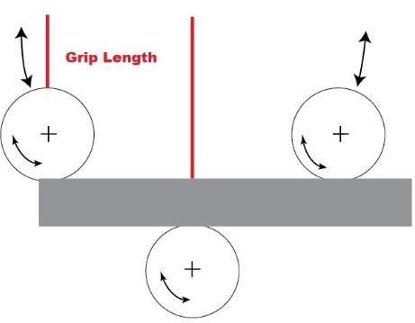
FIGURE 4 The grip length is the distance between the far top roll and the bottom roll. The longer the grip length, the more leverage the machine has to induce a bend. Symmetrical bending occurs by sending the workpiece back and forth in multiple passes. In asymmetrical bending, the far top roll (the top left in this image) and the bottom roll are used to induce bending, often in a single pass.
That extra working makes a difference that can affect how profile bending operators set up their machines. In some cases, the extra work hardening that comes from certain tube production techniques (such as forming into a round and then a rectangle, instead of directly into a rectangle) actually induces cold-working stress into the tube’s side walls. Whether this helps or hinders a bending operation depends on the application. In some cases, the work hardening helps mitigate distortion effects during a tight-radius bend, sometimes making a single-pass bend a little easier. On the other hand, a stiffer wall also can increase the chances of overworking the material, depending on how many passes an operator uses and the severity of the bend.
Whether operators are bending open or closed profiles, tool choice is critical. The tools need to fit the profile yet not be so tight as to negatively affect workpiece shrinkage and growth. A tool that’s too tight can cause localized distortion and, at worst, actually gouge the material surface.
When operators need to bend an open profile like an angle or beam, they have fewer distortion-mitigating tools at their disposal. Beyond tool choice and fit-up, bender-rollers must choose a correctly sized machine, one with sufficient forming tonnage and adequate grip lengths—enough to provide the needed leverage to reduce distortion, but not so long that they will require an excessively long sacrificial straight section. Many modern three-roll benders also have traction units that support beam flanges to mitigate deformation (see Figure 5).
When operators work with tubular sections, they might choose to use a mandrel, and if they do, how that mandrel fits can be critical. When a bender-roller receives material, the operator usually will measure the ID and OD to ensure they are within the mill’s tolerance range, then choose or order a mandrel to suit.
Mill tolerances add complications too. If a mandrel is machined to fit the low end of a tube’s tolerance, yet the received material is at the high end of the tolerance, the mandrel might not provide sufficient support. Conversely, a too snug mandrel can inhibit material growth and shrinkage, which can lead to localized distortion. If tolerances are especially critical, mandrel toolmakers request several feet of the material to ensure the mandrel’s designed to fit.
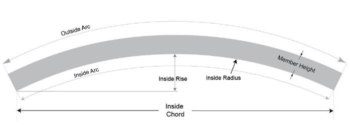
The design guide from AISC does specify standard tolerances for curved steel, as calculated by the inside chord and inside, or mid-ordinate, rise (see Figure 6). If a member is 10 ft. long or less, standard tolerances allow for +/-0.125 in. on the mid-ordinate rise. “But the longer the member is, the more deviation is allowed on that mid-ordinate rise,” Pecho said. Regardless, tolerances can change depending on various factors, all of which are spelled out in the AISC guide.
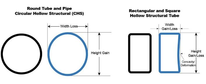
The AISC guide does not provide standards for distortion tolerances, however. As Pecho explained, distortion tolerances vary from shop to shop and even from job to job. As a rule, many topnotch bender-rollers aim to hold a tolerance (compared to the nominal dimension) of 5% growth and 5% shrinkage in square and rectangular tube and open shapes, along with 5% ovality with round shapes (see Figure 7). As tubing sizes get large—especially with “jumbo sized” tubes—that tolerance figure for shrinkage, growth, and ovality could be between 7% and 10% and still be considered acceptable when doing reduced-strength calculations.
These figures are maximum allowable distortion tolerances a bender-roller touts, though typical work can be formed to a far tighter tolerance. “We see distortion tolerances of curved square and rectangular hollow structural sections normally being between 1% and 2%,” Pecho said. He added that if you look closely, you can see the distortion, such as a slight concavity on the inside radius wall. “But it’s still a structurally sound piece.”
Regardless, structural integrity is the true measure of a curved member’s fitness for service, which is why the AISC design guide delves into detail with equations showing how a certain amount of distortion affects the workpiece strength. With the strength verified, the one remaining concern regards fit-up requirements.
Like so many others in metal manufacturing, bender-rollers and fabricators can “make it work” in some cases, but the process does involve more time and money. Why go through all the trouble if a thicker side wall will suffice? Sometimes the savings in overall project costs (forming time, potential for delay, etc.) far outweigh the cost of easier-to-bend, thicker-walled material, even with sky-high material prices. Considering curved member distortion from the get-go—with open communication among the designer, fabricator, and bender-roller—can prevent a lot of needless headaches.


The Fabricator is North America's leading magazine for the metal forming and fabricating industry. The magazine delivers the news, technical articles, and case histories that enable fabricators to do their jobs more efficiently. The Fabricator has served the industry since 1970.
start your free subscription
Easily access valuable industry resources now with full access to the digital edition of The Fabricator.

Easily access valuable industry resources now with full access to the digital edition of The Welder.

Easily access valuable industry resources now with full access to the digital edition of The Tube and Pipe Journal.

Easily access valuable industry resources now with full access to the digital edition of The Fabricator en Español.
In this episode of The Fabricator Podcast, Caleb Chamberlain, co-founder and CEO of OSH Cut, discusses his company’s...


