


Metal Forming Specialist
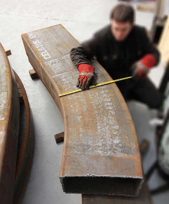
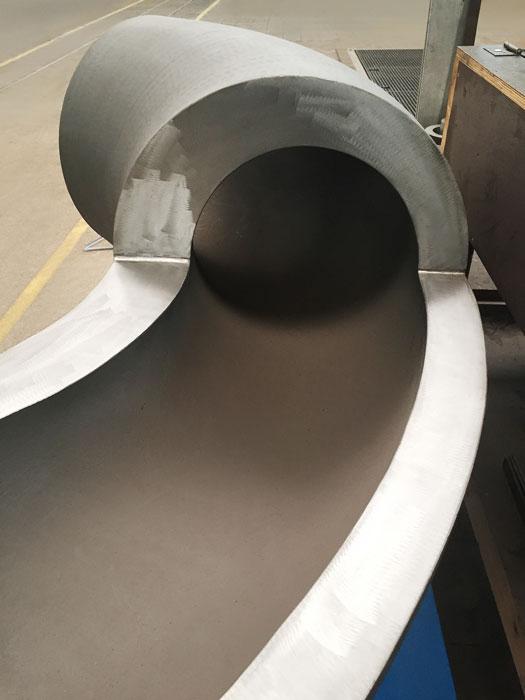
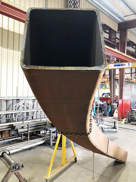
Figure 1
This 18- by 8- by 0.75-in. section was induction-bent to a 6-ft. centerline radius. Photo courtesy of Inductaflex.
For years now building architects and engineers have dreamed up creations with tubes that travel in wild curves and tight bends. They’ve been challenged to design a building like no other, a structure built to impress. Of course, to make tubes and structural sections curve wildly, they need to be bent to tight radii, so they simply can’t be made with conventional bending methods.
Consider an 18- by 12- by 0.75-inch hollow structural section (HSS) curved on the strong axis. Using conventional technologies, many tube bending operations might list 45 feet as the minimum centerline radius for such a section. But what if designers want this profile bent to a 6-ft. centerline radius? Here, induction bending can play a critical role (see Figure 1).
Induction bending can form tubes, pipes, and all structural shapes (see Figure 2), including W sections, HSS, and channel sections, with achievable bend radii from 3D to 10D (or a centerline radius from three to 10 times the workpiece diameter), depending on the exact cross section. For instance, a 20-in.-diameter pipe can be bent to 3D, or a 60-in. centerline radius.
As its name implies, induction bending heats the material at the tangent point as it’s being bent. As shown in Figure 3, a tube, pipe, or section is clamped at the rear (1) and at the front (5) to a pivot arm (6), also called the bend arm or radius arm. The arm’s length roughly equals the radius being formed in the workpiece. The workpiece then passes through a shaped inductor ring or coil (4), manufactured to the shape of the part being curved.
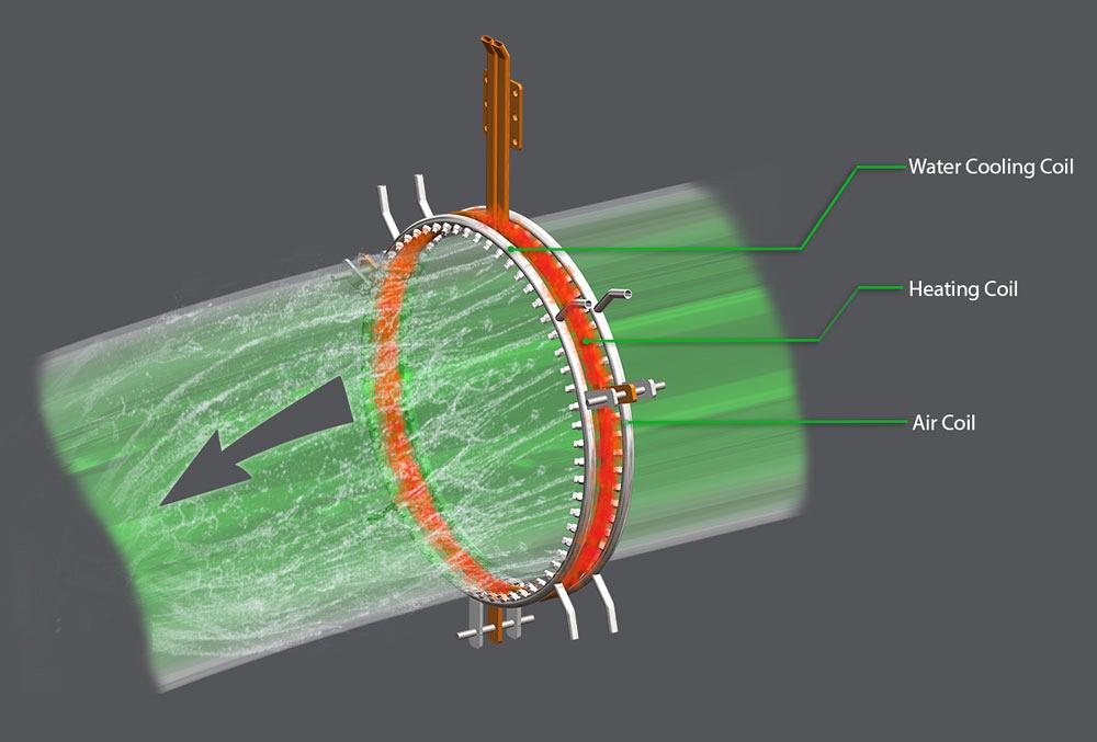
The inductor coil heats a narrow circumferential section of the profile to between 1,560 and 2,012 degrees F (see Figure 4). To heat the section, the coil generates a localized magnetic flux and induces an electric current in the pipe underneath the coil. The material resistance then creates the heat band necessary to bend the pipe.
The inductor ring normally consists of three coils: a heating ring in the middle, a water quench ring, and an air ring. Because of their speed and stability during bending, thicker pipes are not always quenched. But to bend thinner sections, the system needs to cool the work to maintain a narrow heated area as the profile moves through the heating coil. Such quenching is critical for retaining a good shape after bending.
Once the temperature is reached, the pusher clamp (“1” in Figure 3) pushes the workpiece as it bends at the heated area as the pivot arm guides the work through the bend. Springback is allowed for here when setting the radius arm.
A PLC linked to a temperature sensor controls the speed, which depends on the material type, workpiece diameter, thickness, and bend radius. The speed ranges from 10 inches per minute (IPM) down to 0.25 IPM for very heavy, thick-wall alloy material.
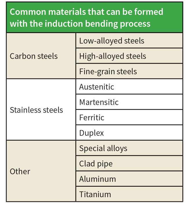
A variety of materials now can be formed with induction bending (see Figure 5). How do material properties change after bending? This depends on the material and the process settings used. The controlled heating and quenching often produces a fine-grained structure that increases tensile strength in the material.
At the same time, though, the quenching produces a harder surface, in some cases a little harder than required. This can necessitate heat treatment after bending, though it’s possible to avoid heat treatment with careful setup on modern machines. Regardless, if a fabricator has work requiring high-quality alloys, it should work with bending companies with a good track record bending the specific material grade and, ideally, have relevant testing data.
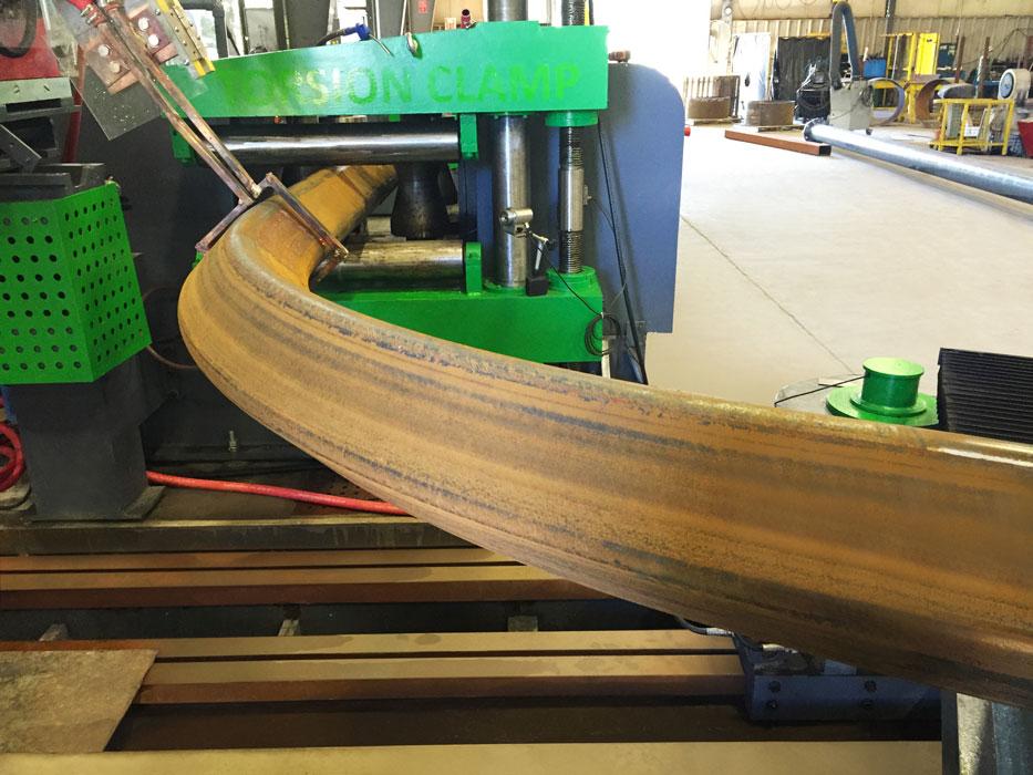
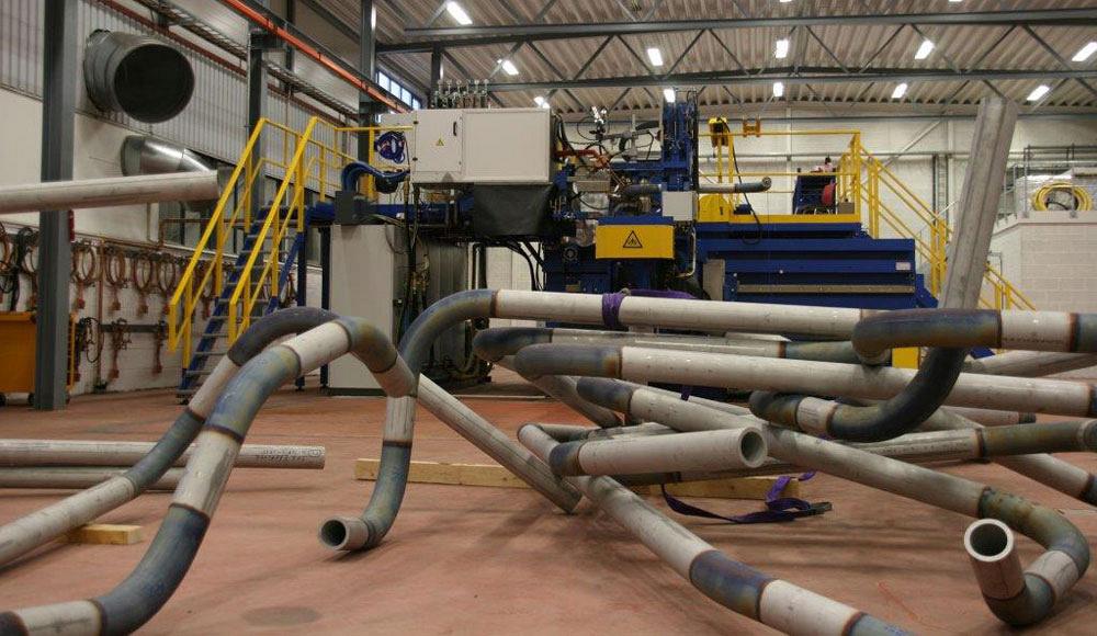
Figure 2
A hollow structural section (HSS) is induction-bent in a diamond orientation. Photo courtesy of Kubes Steel.
Induction bending commonly handles workpiece sizes from 2 to 36 in. OD, although some machines on the market handle up to 108-in.-dia. pipe.
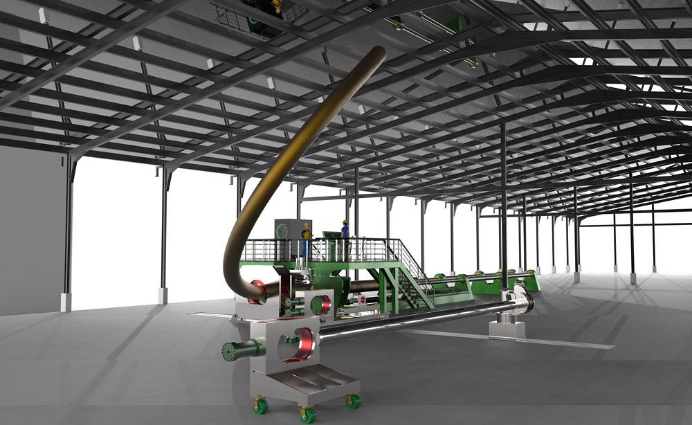
Machines normally have supporting structures to enable long pipes to be formed. A big reason to form long pipes is to reduce wasted material. Forming long pipes also allows for more efficient, high-quality automatic welding for joining pipe sections together.
Although induction bending can achieve bending radii far smaller than cold bending, the process still can cause considerable changes in wall thickness, particularly when forming extremely tight radii.
Still, such thinning can be predicted and thus accounted for when designing the process. For instance, consider a project that requires a minimum wall thickness of 0.75 in. for a 2D pipe bend, achieving a centerline radius that’s only twice the pipe diameter. This project may well require 1-in.-thick-wall pipe to account for the wall thinning on the extrados (outside wall of the bend). Accounting for wall thinning is normal for any kind of tube bending, but in this case, because the bend is extremely tight, the wall thinning is much greater.
Even induction bending has its limits. Induction bending a thin-wall pipe section can cause distortion, and the pipe can end up being out-of-round. The traditional solution has been simply to increase the wall thickness—but this, of course, increases costs.
Recently, however, special tooling has allowed thin-walled pipe to be induction-bent and retain its roundness. This has led to significant cost savings that come from material savings and lighter structures that require smaller foundations.
Kersten Europe, a large bending operation with plants in Europe and the Middle East, recently tested this new technique on a project for Al Wasl Atrium in Dubai (see Figure 6). The company achieved less than 1 percent ovality on very thin walls and bends ranging from 1.5D (that is, a centerline bend radius that’s 1.5 times the pipe diameter).
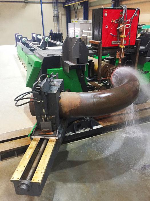
Careful, controlled heating methods have enabled the forming of extremely thick sections, resulting in ever improving cross-sectional and metallurgical properties. This includes the forming of 30-in.-dia., 4-in.-thick P91 alloy pipes. As shown in Figure 7, a machine has successfully bent 4-in.-thick, 25-in.-outside diameter (OD) P91 alloy to a 4-ft. radius.
Another area of advancement is streamlined spool bending (see Figure 8). This has included automatic loading and handling, which has reduced costs.
Although induction bending has been around for decades—its roots go back to Eastern Europe in the 1960s—it remains a niche process, but it’s quickly evolving. In fact, major advancements now are on the immediate horizon. They include spiraling (see Figure 9) and, soon, 3-D induction bending. Within the next year, machines will be able to induction-bend virtually any shape in three dimensions (see Figure 10). Typical applications will include curved stair structural parts as well as 3-D structural parts for modern buildings.
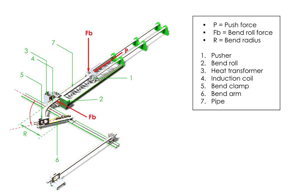
Figure 3
An induction bending system induces localized heat to bend workpieces to tight radii. Image courtesy of Inductaflex.
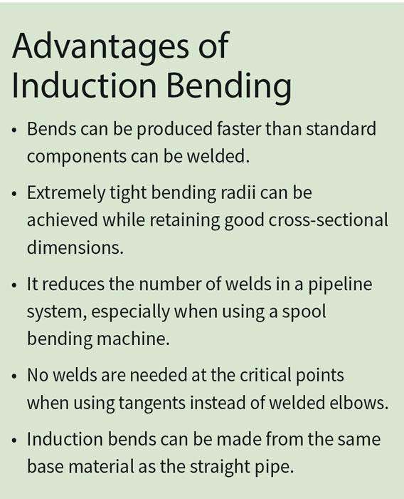
While not for every situation, induction bending has plenty of advantages, including its predictability. Tightly controlled heat input and speed make the resulting wall thinning and ovality predictable—a huge benefit for critical applications.
For the right job, the process minimizes welding, reduces wall thickness requirements, and, ultimately, reduces overall costs significantly. All this makes those wild curves and tight bend radii possible, be they on fanciful buildings or complex industrial structures.
Craig Barnshaw is metal forming specialist at Inductaflex Ltd., www.inductaflex.com, represented in the U.S. by Trilogy Machinery, P.O. Box 70, Belcamp, MD 21017, 410-272-3600, www.trilogymachinery.com. The author thanks Cojafex, www.cojafex.com, for its contribution to this article.

The Fabricator is North America's leading magazine for the metal forming and fabricating industry. The magazine delivers the news, technical articles, and case histories that enable fabricators to do their jobs more efficiently. The Fabricator has served the industry since 1970.
start your free subscription
Easily access valuable industry resources now with full access to the digital edition of The Fabricator.

Easily access valuable industry resources now with full access to the digital edition of The Welder.

Easily access valuable industry resources now with full access to the digital edition of The Tube and Pipe Journal.

Easily access valuable industry resources now with full access to the digital edition of The Fabricator en Español.
In this episode of The Fabricator Podcast, Caleb Chamberlain, co-founder and CEO of OSH Cut, discusses his company’s...


