


Technical Services Manager
A firm foundation is the key to building anything successfully. This basic idea also holds true with a gas metal arc welding (GMAW) machine setup, especially when you’re welding aluminum.
Most GMAW machines are originally configured by the equipment manufacturer to weld with steel wire. Unlike steel wire, aluminum wire lacks rigidity (i.e., column strength). During aluminum GMAW, the entire wire feeding system must be configured correctly and specifically for aluminum to avoid headaches and downtime from fixing birdnests and other wire feed problems.
Welders who are more familiar with steel GMAW might think wire feeding issues in aluminum GMAW are the norm because these problems rarely occur with steel. By simply familiarizing yourself with the five main components that affect wire feeding, you can ensure that each is set and maintained in a way that will encourage optimal wire feeding quality.
The first piece of the puzzle is the wire itself, either spool or drum. The goal is to have a GMAW system that feeds wire continuously without interruption. If not, your day just got much longer, management is unhappy with the lack of production, and someone is probably spending valuable time on the phone with the wire supplier because “it’s always the wire!” However, assuming the wire is manufactured and packaged properly, mishandling can be the root cause of your feeding problems.
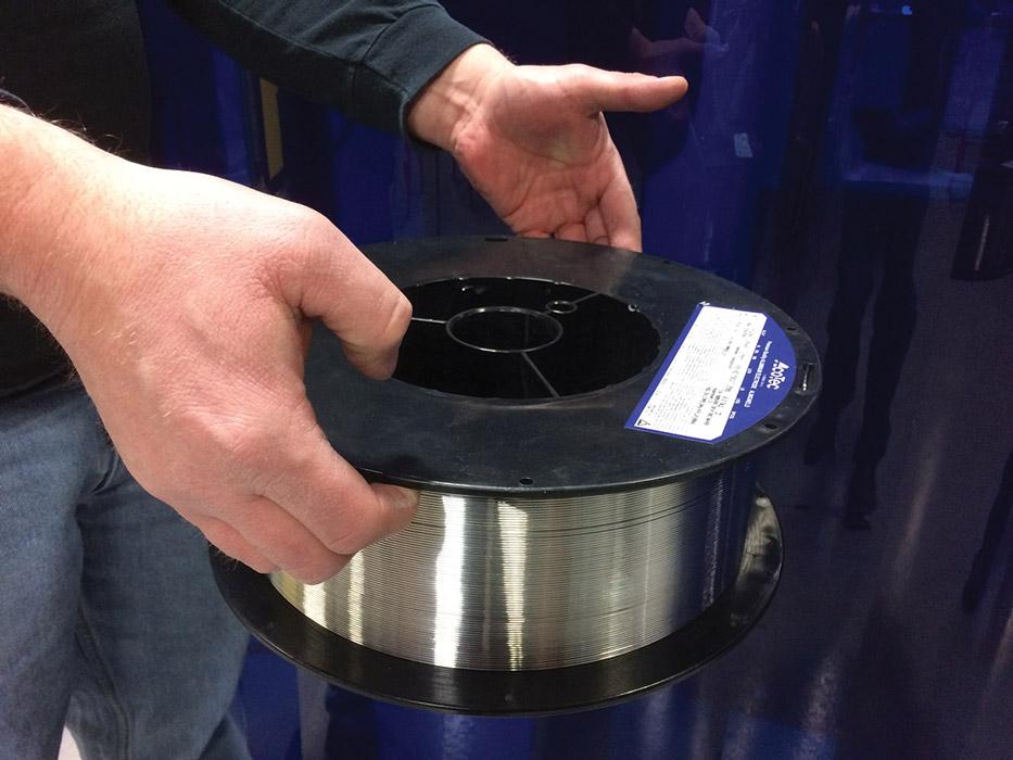
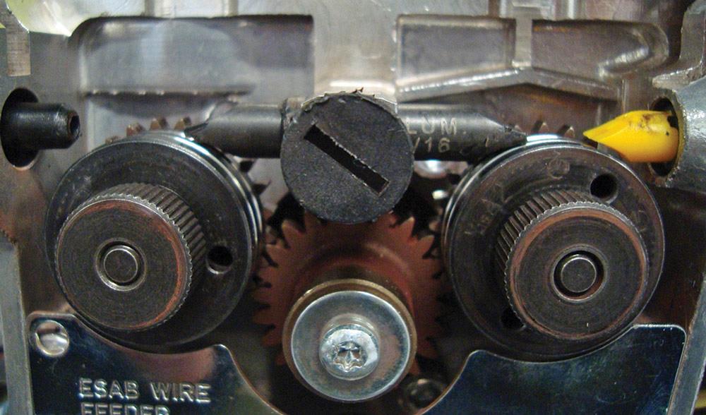
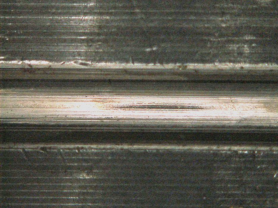
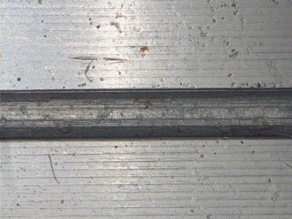
For example, don’t lift spools of wire by only the top flange. Lift either by the hub or by grasping the bottom flange. There is enough flex in the flanges of many spools to allow the wire to slip in between the next layer. If this happens, the wire can get pinched in between wraps of the subsequent layer, resulting in a feeding interruption (see Figures 1, 2, and 3). If you are using drum packaging, make sure they always remain vertical and that the wire is properly secured before they are moved.
Another consideration is the brake tension of the spool spindle. The brake should be set just tightly enough so that the spool does not spin freely when the feeder stops pulling the wire. If it’s too tight, the drive rolls may start slipping, which will typically cause the drive roll grooves to build up with aluminum. If the brake is too loose, the spool may continue to turn and the wire can jump over the spool flange, which will generally cause a tangle.
On most wire feeders, the wire will rub on some sort of inlet guide before it reaches the drive rolls. Although most inlet guides are plastic, this is a component that you need to inspect to ensure it is not metallic or grooved from the wire rubbing on it. This also applies to any guide that may contact the wire. Center guides (if present) and outlet guides should be tapered with a contour matching the OD of the drive rolls to allow their ends to be as close to the rolls as possible (see Figure 4).
When feeding aluminum you must eliminate all areas where the wire is not supported or encapsulated. The soft aluminum wire will always take the path of least resistance, so the machine must be set up to ensure the wire has a clear and controlled path to the contact tip.
The most common setup issue with drive rolls is excessive pressure, which can cause the wire to become misshaped, leading to excessive burn-backs. Excessive pressure can also contribute to wire shavings, especially if the drive roll grooves are incorrect or misaligned.
So how much drive roll pressure should you use for aluminum? Unfortunately, there is no magic number as multiple variables are involved. The best way to set the drive roll pressure for aluminum is to simply start at the lowest setting and gradually increase the pressure if the wire seems to be slipping under normal operating conditions. The technique used for steel, whereby you feed the wire into an obstruction and increase the pressure until it curls the wire, is not usually recommended for aluminum. That much pressure will generally cause aluminum wire to deform. Also, since aluminum GMAW typically is performed using the spray-arc transfer mode, there should not be any significant resistance to the wire as it leaves the contact tip.
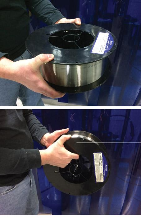
Figure 1and 2
When you are lifting or carrying a spool of aluminum wire, be sure to lift at the hub or by grasping the bottom flange.
The drive rolls must also have the correct groove geometry and be properly aligned (see Figure 5). Aluminum welders have always been told to use only U-grooved drive rolls. While a couple of other options are out there, the U-groove is by far the most common. Once you make sure you have the correct drive roll groove size, you should also take a look at the quality and geometry of the grooves under magnification (10x is usually enough) to ensure the grooves are smooth.
It is not uncommon to see rough contact surfaces within the grooves or sharp edges where the groove meets the outer surface (see Figure 6). If either of these features is not adequate, you can either try a different manufacturer’s roll or polish the ones you have. Any fine-grit polishing stone that will fit into the groove should do the trick. In fact, many companies have developed a routine of polishing all of their new drive rolls before they are made available to production.
Most wire feeders have “floating” drive rolls. This means they have a little bit of side-to-side movement, allowing the wire to basically guide the rolls into alignment. However, if anything becomes lodged between the drive roll and the face of the gear, the roll may not float anymore, and the edges of the wire grooves could deform or gouge the wire. A simple way to prevent this is to pull the rolls off with every one or two wire spool changes and make sure the rolls and gear face are clean.
One of the most common misconceptions is that a push/pull arc welding gun is required for aluminum GMAW. While using a push/pull setup will typically minimize feeding difficulties, it is not always required. Many believe the need for a push/pull gun is based on the gun length. However, the stiffness of aluminum wire can vary greatly depending on the alloy. For this reason, arbitrary gun lengths are not always practical.
Soft aluminum alloys such as 1XXX, 2XXX, and 4XXX have lower column strengths than hard alloys like 5XXX. For example, 0.047-inch-diameter 5356 typically can work in a 10- to 12-foot push-only system that is properly configured without any issues, but 4043 alloy in the same system may have problems feeding since it is much less rigid. No matter how long the gun may be, minimizing the bends and loops between the feeder and the contact tip will significantly improve overall feedability.
Regardless of what length or style of torch you choose, you should consider using a nonmetallic torch liner—Teflon®, nylon, and graphite are the most common options available. Some aluminum liners now have a metal outer coil with a nonmetallic sleeve. This makes them look very similar to steel liners, so be certain the inside diameter (ID) of the liner is correct for your application. Push/pull guns also incorporate a neck liner between the pull wheels in the gun and the diffuser. While these are often coiled metal liners, nonmetallic should also be considered here. Basically, the goal is to ensure nothing in the feeding system can scrape the wire and cause shavings that could plug the liner or back of the contact tip.
Knurled drive rolls can come into play in either the feeder cabinet or a push/pull system. Generally speaking, knurled drive rolls are not suitable for aluminum GMAW because they slightly cut into the wire, generating a significant amount of shavings that plug the liner and/or contact tip. Knurled rolls are often found in the gun on push/pull systems, but the welders who use them have decided to deal with the shavings in the short neck liner to gain a better grip on the wire. While a system that is properly set up and maintained shouldn’t need the added grip, many companies put them in the push/pull gun as an added measure to help avoid burnbacks and feeding inconsistencies.
The last component is the contact tip. For a variety of reasons, this is another common place for setup errors to occur. The two problems most frequently discovered are oversized tips and poorly manufactured tips. A lot of manufacturers make aftermarket tips. While the tips may look the same on the outside, they may contain lower-quality alloys, have manufacturing defects, or have inconsistent bore diameters.
The inlet can be examined with the 10x eye loop to ensure no burrs are left from the chamfering tool. Since many shops don’t have precision pin sets available for checking the ID of the tips, a drill bit of the appropriate diameter can be used to make sure it’s close. Generally, the ID of the tip should be approximately 10 percent more than the wire diameter. You can also use a tip dressing/reconditioning kit to ensure the bore is smooth and the inlet is clean.

The Welder, formerly known as Practical Welding Today, is a showcase of the real people who make the products we use and work with every day. This magazine has served the welding community in North America well for more than 20 years.
start your free subscription
Easily access valuable industry resources now with full access to the digital edition of The Fabricator.

Easily access valuable industry resources now with full access to the digital edition of The Welder.

Easily access valuable industry resources now with full access to the digital edition of The Tube and Pipe Journal.

Easily access valuable industry resources now with full access to the digital edition of The Fabricator en Español.
In this episode of The Fabricator Podcast, Caleb Chamberlain, co-founder and CEO of OSH Cut, discusses his company’s...


