Welding Product Marketing Manager
Robotic aluminum welding is on the rise thanks to a push toward lightweighting. To ensure the process is successful, you must be aware of the differences between aluminum and steel and how those differences affect the weld process and components that you use.
The use of robotic arc welding for high-volume automotive component production is becoming more widespread. Benefits such as better quality and improved consistency combined with a variety of technical advancements for the implementation of gas metal arc welding (GMAW) during the fabrication process have been key reasons behind this.
While welding steel is routine, a growing number of companies, especially truck trailer manufacturers, are transitioning to the use of aluminum parts to meet customer demands for more efficient, lightweight vehicles. Being successful with aluminum, however, requires special considerations to maintain the welding operation.
Recent advances in power sources are now moving the discussion of applying arc welding robots from “Can I weld my part?” to “What do I want the weld to look like?”
GMAW uses a consumable electrode that continuously feeds material to form a weld deposit, allowing for fast travel speed and providing a process tolerance (weld joint repeatability) for robotics that is maintainable at plus or minus half the wire diameter. Ideal weld cosmetics for GMAW are smooth, uniform beads, without sharply defined solidification lines (ripples).
Gas tungsten arc welding (GTAW) uses a nonconsumable electrode to form the puddle while the welder skillfully balances the melting of base material with the addition of filler material, creating defined solidification lines (ripples) that form the bead. The “stacked dime” or “layered penny” appearance produced by GTAW are aesthetically pleasing to some and represent hand-crafted quality by others.
Aluminum’s properties are quite different from steel’s, and you must understand them to successfully automate GMAW of aluminum alloys.
Thermal Conductivity. Because of its high thermal conductivity, aluminum is difficult to heat at the start. Once heated, it melts at a lower temperature. This can make the fabrication process more difficult when welding thick to thin sections because heat usually absorbs into the thicker section, making it tough to fuse or join a thinner section.
Material Softness. Aluminum is softer than steel and can present challenges for feeding the wire electrode. Advancements in through-arm robots have helped reduce several problems that have plagued the wire feeding of aluminum in the past.
Color and Fluidity. Perhaps the most obvious difference between aluminum and steel is that aluminum does not change color when heated, whereas molten steel turns red to orange. The lack of color change can present a challenge for welders who are learning to fabricate with aluminum because it is very fluid. At times working with aluminum may seem like welding a pool of water as it is pushed.
Solidification Rate. Aluminum’s high solidification rate allows for faster welding speeds than with steel. Fabricators need to keep in mind, however, that the fast-freezing temperature of aluminum can impact the crater at the arc end.
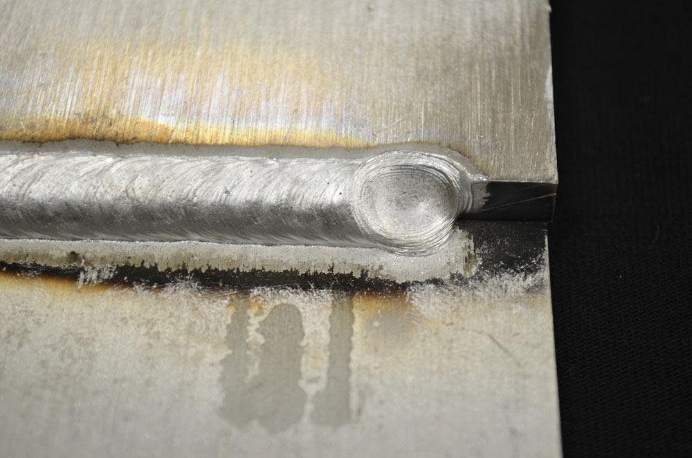
Figure 1
When a weld is completed, the
aluminum puddle freezes fast, leaving a
depression or crater that must be filled.
Ignoring aluminum’s unique properties and failing to implement certain process changes during GMAW could lead to burn-through, warping, or lack of fusion that could ultimately compromise a final weld’s integrity, slowing production because of the need for rework. Here are a few robotic aluminum GMAW process changes to consider.
No. 1: Arc Starting
The high thermal conductivity of aluminum often leads to cold lap at the arc start, and finding ways to get enough heat into the part to help fuse the puddle can be challenging. For this reason, use a higher current, or “hot start,” at the beginning of the weld. Acquiring a robot that supports this process with a higher amperage is ideal, because it is best to use high current in conjunction with motion to avoid buildup and compounding the cold lap.
Once the material is heated, it will melt at a low point. Within 10 to 15 mm of travel, reduce the current, and continue movement so that you can make the weld at a lower heat input. Sometimes a function is available that allows the ramping of the current during the GMAW bead. This can be helpful when the robot is welding over an extrusion with a rib, as the difference in mass can affect the look of the weld bead.
You can balance the parameters to reduce the profile of the bead at the start. Some power sources can reverse the wire on contact, creating a “lift start,” which is a more stable arc start.
No. 2: Dual Pulse
While pulse welding normally is used with aluminum, a successful process variation is alternating between dual settings of a high and low current (2 to 5 Hz) to produce a GTAW-like appearance or ripples in the bead, creating aesthetically pleasing welds. The fast solidification rate of the aluminum puddle allows this to happen, whereas with steel, it is not as pronounced. Often programmed as a percentage, dual pulse creates a unique sound as the power supply alternates between high wire feed speed and low wire feed speed.
The other parameter that is key for dual pulse is frequency, which has a direct effect on the spacing and size of the ripples. Lower frequency produces greater spacing, while higher frequency reduces the spacing between the ripples. Dual pulse capability can be a feature in the power source itself, or sometimes it can be an element of the robot control, whereby you can adjust certain parameters in the robot welding files or program.
Welds with distinct ripples in the bead have the potential to collect dirt and grime, resulting in faster deterioration. This is especially true for fuel tanks and truck bodies when they are exposed to the outdoor elements. For this reason, many truck manufacturers use a smooth bead profile, a result of regular pulsed GMAW, that is often used for container welds. Newer robot controllers should provide the option of turning off dual pulse capability. However, if that feature is not available, you can adjust the frequency to produce a smooth, nonlayered appearance.
No. 3: Arc Ending—Crater Fill
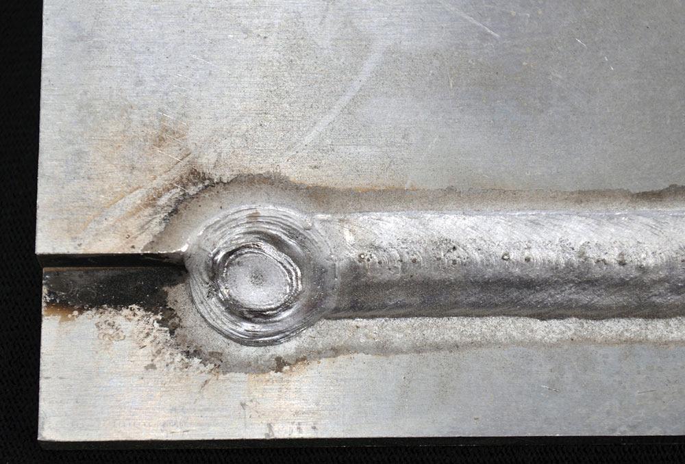
Figure 2
To fill a depression during GMAW, use a single- or two-step fill process or employ “back stepping.” A two-step, arc-off sequence requires a short duration at a low current (less than 100 amps) after the first stop.
In addition to varied settings at the arc start, an aluminum weld can benefit from multiple settings at the end of the arc. When a weld is completed, the aluminum puddle freezes fast, leaving a depression or crater that must be filled. Filling it at a high current while shutting down will likely leave a depression as well (see Figure 1).
To fill a depression during GMAW, use a single- or two-step fill process or employ “back stepping.” A single-step process simply fills, leaving a slight depression; a two-step, arc-off sequence requires a short duration at a low current (less than 100 amps) after the first stop (see Figure 2). To back-step the crater, go to the end of the weld and reverse the robot’s direction by a few millimeters before filling the depression (see Figure 3). This allows you to terminate the weld pass outside of the stress region at the end of the weld, reducing the risk for weld size variation that might create a stress riser and cracking (if subject to fatigue loading).
No. 4: Water-cooled Torch
Because aluminum welding is pulsed welding, it tends to heat up the wire, causing it to swell and stick in the tip. For this reason, use a water-cooled torch to help reduce those feeding issues.
No. 5: Gas Coverage
While you’d typically use a contact tip extended beyond the nozzle to weld steel, you should use a recessed tip to weld aluminum. Why? Because it can improve gas coverage if the joint access allows.
Robotic Aluminum Welding: How to Make It Work for You
There are three basic wire feed configuration options for robotic aluminum welding. Most steel welding robotic systems have a wire feeder on the arm, which pushes the wire out without much problem. For aluminum, a push/pull gun—a wire feeder in the torch with an assist behind it—is ideal. However, process considerations or financial restrictions may dictate what type of equipment you choose to use.
1. Push-Only Feeder. Although not ideal, a standard robotic welding system with a push-only feeder can weld aluminum, but certain precautions apply.
Although push-only wire feeding is the least expensive way to weld aluminum, it is prone to birdnesting. This method, however, can be used with a standard robotic welding system, often used for steel.
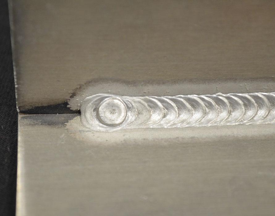
Figure 3
To back-step the crater, go to the end of the weld and reverse the robot’s direction by a few millimeters before filling the depression.
2. Pull Torch. Consider replacing your standard torch with a motorized-pull torch. Integrated with the power source, pull torch units pull the wire from wire drums located within 5 meters of the robot cell. This method greatly improves the feedability of the wire, reducing the chance of birdnesting versus push-feeding systems.
3. Push/Pull Feeder. The recommended method for exclusively welding aluminum robotically is a power source and feed system designed specifically for aluminum applications. This type of unit consists of:
This type of system is fully integrated and offers the most control over the weld start and end, as well as the overall weld condition. Typically synchronized by the power source control, the pull feeder can be synchronized with the push feeder, running in the same direction at all times. Depending on the application, some servo pull torches can weld without using the push feeder, but if there is any doubt, contact your manufacturer.
Chris Anderson is associate chief engineer at
Yaskawa America Inc., Motoman Robotics Division, 937-847-6200, www.motoman.com.

The Welder, formerly known as Practical Welding Today, is a showcase of the real people who make the products we use and work with every day. This magazine has served the welding community in North America well for more than 20 years.
start your free subscription
Easily access valuable industry resources now with full access to the digital edition of The Fabricator.

Easily access valuable industry resources now with full access to the digital edition of The Welder.

Easily access valuable industry resources now with full access to the digital edition of The Tube and Pipe Journal.

Easily access valuable industry resources now with full access to the digital edition of The Fabricator en Español.
In this episode of The Fabricator Podcast, Caleb Chamberlain, co-founder and CEO of OSH Cut, discusses his company’s...