Global Product Manager—Tweco Welding Torches
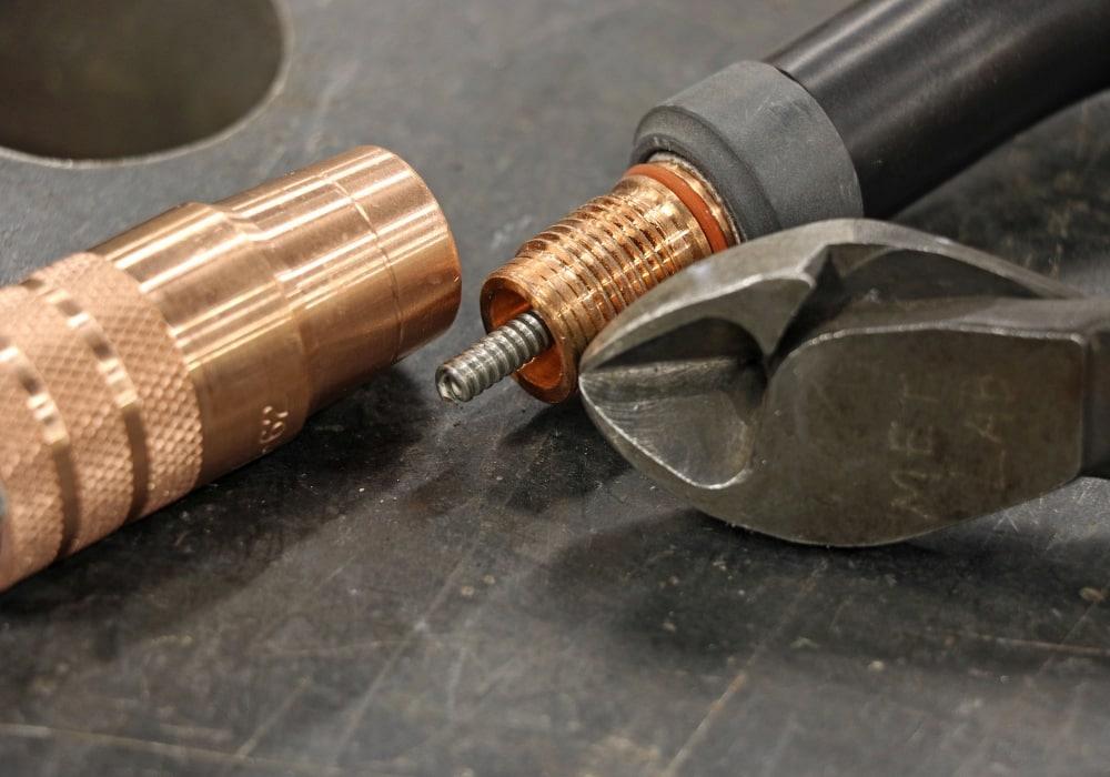
For a clean cut, orient the side clippers as shown. Notice the line on the shielding gas cup, which provides a handy guide for cutting the liner to the correct length. Images: Tweco
Are you frying bacon or banging your head?
A well-tuned GMAW system with all components operating in harmony sounds a lot like frying bacon. On the other hand, burnbacks, birdnests, spatter, porosity, and other issues indicating one or more components need attention can cause you to bang your head in frustration.
All components of a GMAW system need to operate in harmony to produce good welding results. If your once finely tuned system starts to stumble, take a few minutes to check key components for wear. Taking the time to address the situation is far more preferable than grinding spatter or removing a bad weld, and thus banging your head against the wall.
Welders need to set themselves up for success, and that starts with using the correct shielding gas flow rates. Taking a “more is better” approach and setting flow rates up to 40 CFH causes the shielding gas to swirl, pull in the surrounding atmosphere, and contaminate the weld.
To ensure a smooth, laminar gas flow and good coverage of the weld puddle, be sure to set flow rates according to the gun manufacturer’s recommendations. Because of the variety of contact tips now available (traditional threaded, drop-in style, and ported), flow rates can vary. Some consumables operate better at 35 CFH, while others operate better at lower flow rates because the gas spends more time inside the nozzle.
If you’re worried about wind blowing away the shielding gas, set up wind screens or use a self-shielded FCAW wire or the SMAW process. Watch out for overhead doors opening and closing near welding areas as well, as those are known causes of porosity.
With bulk gas systems, the flow rate at the gun may vary with demand or between shifts. If you suspect a flow rate problem, try installing a flowmeter at the back of the wire feeder or use a wire feeder with a built-in flowmeter.
Gun liners that are worn or clogged with wire shavings and particulate create excess friction for the wire, ultimately leading to a “stick-slip” phenomenon and erratic feeding. When the wire slips, your first instinct may be to increase drive roll tension. Unfortunately, doing so crushes the wire and generates even more shavings, further increasing drag on the wire and placing even more strain on the drive motors.
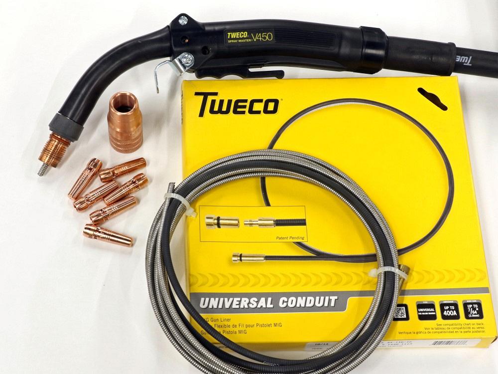
MIG guns, liners, tips, and nozzles all work together to create a good arc.
Given the relatively low cost of a gun liner, consider replacing the liner on a consistent basis, perhaps after every 60 to 120 lbs. of wire, depending on conditions or wire brand. Some wires contain more drawing compound on the surface and clog liners more quickly.
Use a nylon liner for aluminum wire and a stainless steel liner for stainless steel wire (and be sure to use a dedicated gun for stainless steel wires to avoid carbon contamination). Gun liners come in several diameter ranges, such as 0.030 to 0.035 in., 0.040 to 0.045 in., 0.052 to 1/16 in., and so on. Select the correct liner diameter to match the wire diameter, but don’t use an oversized liner as it could give the wire an opportunity to “snake” and buckle inside the liner.
To replace a liner, remove the old one and lay the new one next to it on a flat surface. Cut the new liner to the exact same length as the old one, making sure that the surface is clean beforehand. Alternatively, some gas nozzles have a line on them to indicate how far the liner should protrude from the conductor tube. Cutting the liner to the correct length is important because a short liner can lead to an erratic arc or create a space where wire could hang up, leading to a birdnest. For a cleaner cut, orient the cutters so the cup faces out, and use a hand file to remove any burrs.
Don’t be stingy with the contact tips. If you can see the tip orifice becoming too large or oblong instead of round, change it out. Worn tips — plus the excessive wear you can’t see on the inside— lead to an erratic arc and excess spatter. The “keyhole” shape also compromises the position of the welding wire, resulting in poor targeting, meaning the wire might not go where you direct it.
When selecting contact tips, trying to save 50 cents by using low-cost tips is a money-losing proposition. The ability of a tip to conduct electricity and heat depends on the quality of its metallurgy, grain structure, and machining tolerances. Premium tips last longer and deliver more consistent performance because of superior metallurgy and tighter tolerances, and that puts more money in your pocket compared to frequent tip changes.
Wear studies done over the last decade demonstrate that drop-in style/ported contact tips run cooler and last longer than traditional threaded contact tips. They are also easier to change in the event of a burnback, especially with large-diameter wires. That said, threaded tips remain the most popular choice. They come in pure copper (standard life) and copper chromium zirconium (long life) options.
The insulator on a traditional gun also wears over time and the slip-nozzle fit becomes wobbly and loose, which may lead to gas leaks. If that happens, it’s time to replace the insulator and/or nozzle. Some diffusers and conductor tubes have O-rings, which you should inspect and replace if they are worn.
GMAW produces spatter that builds up and interferes with gas flow. You may be tempted to remove spatter by banging the gun on the welding table, but that doesn’t work. Doing so could loosen connections at the front of the gun. Instead, use a pair of welpers or a nozzle reamer to clean the gun. If spatter is stuck to the tip and won’t come off, replace the tip. Clipping or filing spatter off usually destroys the tip anyway. Spatter can also clog gas diffuser ports, so be sure to inspect those as well.
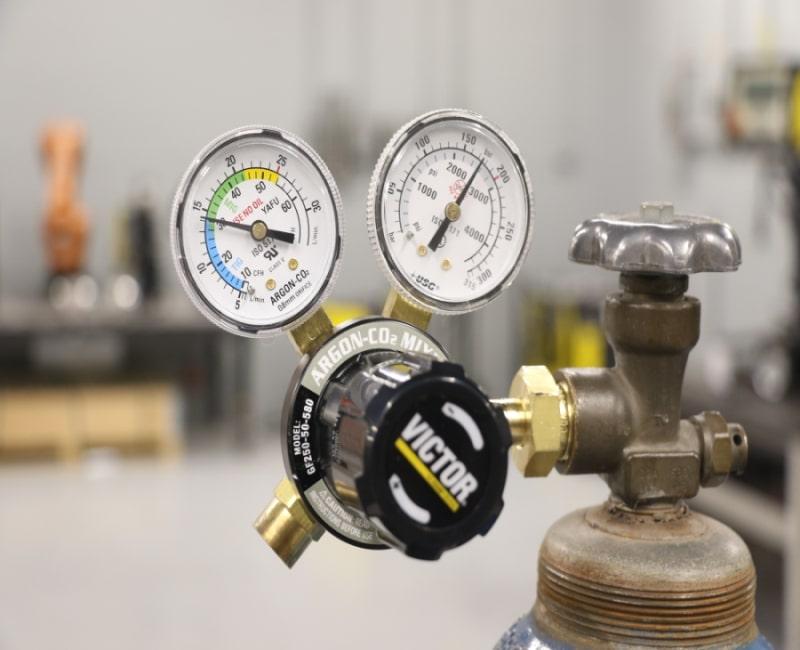
When it comes to shielding gas, more is not better. Be sure to set flow rates according to the gun manufacturer’s specifications.
The wrong contact-tip-to-nozzle relationship can create spatter and porosity. Nozzles come in four types: recessed, flush, protruding, and adjustable slip. Gas shielded cored wires generally require a wire stick-out of ½ to ¾ in. and tend to work best with a recessed nozzle because that provides better gas coverage with a longer stick-out.
Solid wires generally require a stick-out of ¼ to 3/8 in., so a flush nozzle may work better. You can misjudge the correct stick-out with a recessed tip and hold too long of a contact-tip-to-work distance. The solution is greater situational awareness, listening for the sound of a good arc, and checking welding parameters against weld procedure specifications.
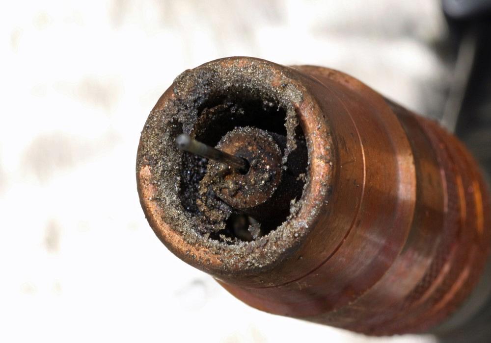
These consumables need cleaning, and the contact tip is nearing the end of its life.


The Welder, formerly known as Practical Welding Today, is a showcase of the real people who make the products we use and work with every day. This magazine has served the welding community in North America well for more than 20 years.
start your free subscription
Easily access valuable industry resources now with full access to the digital edition of The Fabricator.

Easily access valuable industry resources now with full access to the digital edition of The Welder.

Easily access valuable industry resources now with full access to the digital edition of The Tube and Pipe Journal.

Easily access valuable industry resources now with full access to the digital edition of The Fabricator en Español.
In this episode of The Fabricator Podcast, Caleb Chamberlain, co-founder and CEO of OSH Cut, discusses his company’s...