


Contributing Writer
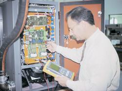
Figure 1Typically, the vee length depends on the mill design, but it should not exceed the tube OD.
Since the 1960s, the workhorse of the tube and pipe industry has been the high frequency (HF) vacuum tube welder. Recently, an increasing number of producers have been installing the HF solid-state welder, in part because of its efficiency, compact design, and high power factor.
Many vacuum tube welders are still in use, however, and operators need to be just as knowledgeable about current vacuum tube maintenance and troubleshooting techniques as they are about solid-state procedures.
This article outlines the maintenance and troubleshooting procedures for each type of welder.
A vacuum tube welder has four major sections: the power supply, which converts alternating current (AC) voltage to direct current (DC) voltage; the oscillator, which converts DC to HF power; a cooling system; and a controls and diagnostics package to monitor and control the welder functions.
To maintain a vacuum tube welder, operators should be completely familiar with the system's technology and adhere to all safety procedures (such as Occupational Safety and Health Administration [OSHA] directives, lockout/tagout, etc.).
Maintenance should be performed every six months or at least once a year, depending on the production schedule. After the welder has been locked and tagged out, all exterior walls and panels should be completely wiped down before initiating the following:
When maintenance is complete, perform a final visual inspection to ensure the system has been reconfigured properly. Then notify the mill operators to energize the system to verify proper operating conditions.
Preventive maintenance is essential on all vacuum tube welders. If operators keep the distilled water clean, keep the interior of the cabinets clean and dry, and check connections and components regularly, welder downtime should be drastically reduced.
Troubleshooting must be performed by fully trained personnel under the guidance of the welder manufacturer. Most welder manufacturers have a service staff available by phone 24 hours a day, 365 days a year.
Operators should never hesitate to contact the manufacturer for help. If a problem cannot be solved over the telephone, the manufacturer will dispatch a field engineer to perform on-site emergency service.
Welder faults fall into several categories: problems outside the welder, in the weld area setup, or in the mechanicals.
If the heat fluctuates without adjustment of the welder controls, the problem could be either impeder saturation or a breathing or rolling vee.
If the impeder is going in and out of saturation, this will be shown as weld current not flowing regularly in the vee and flowing on the inside diameter (ID) of the tube. This typically happens if the impeder does not get enough coolant or the coolant lines become blocked during operation.
The solution is to verify that impeder coolant is flowing properly; if it is, then the strip presentation to the weld point should be examined. The strip must address the weld point in a stable manner (the vee length must remain stable). If it varies, the weld current will vary, causing a noticeable heat fluctuation in the weld.
A similar problem is insufficient heat generated into the weld vee, especially on small-diameter tubing. This can happen because no impeder was used, or it was too small or, depending on the tubing size, the vee length is well beyond the norm for that particular tube outside diameter (OD).
The rule of thumb for HF induction welding is that the impeder should occupy 75 percent of the ID of the tube and should extend .125 inch beyond the apex of the weld rolls, extending upstream through the coil by one coil width.
The more impeder an operator can fit inside the tube without any mechanical interference, the more efficient the welding operation will be. The impeder is the most easily overlooked component but perhaps the most important for welder efficiency.
The vee length should be kept to a minimum. Typically, its length depends on the mill design, but it should not exceed the tube OD (see Figure 1).
Another kind of problem is a short circuit in the welding system, usually noticed by a fault registered by the diagnostics.
When a fault is registered, first visually inspect the system with power off. Check the oscillator, output station, and power supply to identify anything unusual, such as water leaks, burning, arc marks, or damaged or cracked components.
If no obvious problems are found, the system needs to be separated and troubleshooting should begin.
Although their use is increasing, HF solid-state welders have a downside because of their infancy compared to vacuum tube welders, which have been around for almost 40 years.
Even if a vacuum tube welder is 20 years old and its manufacturer is no longer in business, that welder can be maintained by a long-standing competitor because of the common operational attributes of all vacuum tube welders.
With solid-state welders, however, customers must be careful. Manufacturers do not always have the ability to diagnose competitors' equipment because of the diverse technologies of solid-state welders on the market.
A solid-state welder has the same four major components as a vacuum tube welder, except that an inverter section replaces the oscillator.
All of the safety and documentation reviews must be performed, as with vacuum tube welders, followed by the proper lockout/tagout of the equipment and a thorough exterior cleaning of all cabinets and panels.
An acceptable maintenance schedule is once every 12 to 18 months, depending on production requirements. Maintenance should include the following:
On solid-state welders, the circuit design, lower voltages, and circuit-board-mounted technology help to increase reliability and mill uptime. When problems do arise, however, fault diagnostics may be needed.
Most solid-state welders today are delivered with a computer graphics diagnostic package. If a fault occurs, the diagnostics package directs operators to the most probable cause. A modem can also be installed to access the system remotely to aid in troubleshooting.
With any welder, the most common fault is a short circuit, caused by an insulation breakdown or component failure.
When a fault does register, the diagnostics should aid in directing operators to the first area to investigate, which is usually outside the welder proper and in the area of the coil or contacts:
These basic steps of general preventive maintenance and troubleshooting for both vacuum tube and solid-state HF welders should assist in keeping welders online and producing pipe or tube.
To achieve this result, operational personnel must be fully trained on all aspects of safety and equipment. If problems arise that cannot be readily addressed, operators should contact the welder manufacturer for technical assistance.

The Tube and Pipe Journal became the first magazine dedicated to serving the metal tube and pipe industry in 1990. Today, it remains the only North American publication devoted to this industry, and it has become the most trusted source of information for tube and pipe professionals.
start your free subscription
Easily access valuable industry resources now with full access to the digital edition of The Fabricator.

Easily access valuable industry resources now with full access to the digital edition of The Welder.

Easily access valuable industry resources now with full access to the digital edition of The Tube and Pipe Journal.

Easily access valuable industry resources now with full access to the digital edition of The Fabricator en Español.
In this episode of The Fabricator Podcast, Caleb Chamberlain, co-founder and CEO of OSH Cut, discusses his company’s...


