Contributing Writer
 |
Robotic gas metal arc welding (GMAW) of aluminum alloys has been an industry challenge for many years. Early attempts made to automate this process typically failed. The failure of early automated cells was associated with a lack of process experience or improper equipment selection. This failure rate put a "high risk" label on robotic aluminum applications, so many have avoided the practice of automating GMAW.
As the automotive industry strives to maximize the efficiency of its vehicles, it has increased its use of aluminum alloys. This increase has forced robotics manufacturers and the welding industry to develop automated systems that can meet the changing requirements successfully. As the robotics industry continues to understand better the characteristics of aluminum, several theories have surfaced about best practices; however, you should know the fundamentals of and basic requirements that a robotic system should comply with.
Simply having the basic components of a robotic GMAW system (see Figure 1) doesn't guarantee a successful aluminum application; how the components are applied and maintained determine this. Several key components and controls make a welding application successful.
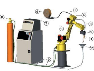 |
| Figure 1 A typical robotic system should have this basic configuration: 1-Quick-change Torch 2-Servo Torch Four-roll Drive 3-Utility Cable 4-Utility Junction Box 5-Insulated Wire Conduit 6-Welding Wire 7-Digital Weld Power Supply 8-Gas Supply 9-Robot Connection Cables 10-Robot Arm 11Work Lead. |
The weld power source should be coupled with the robot directly through a digital network. The robot becomes the interface to the weld equipment, offering a single point of control to adjust parameters and eliminating the need for additional programming devices.
With a digital network, commanded outputs are absolute. The time it takes for the robot to talk to the power source is minimized, making on-the-fly process changes almost instantaneous.
For the operator, these can mean a decrease in setup time, an increase in integration efficiency, and accurate process control. Accurate process control is critical when welding aluminum. The objective should be to have maximum process control through a single source, the robot.
The wire drive design should be robust and able to feed the wire at the commanded rate without wire slippage. A high-torque, four-roll, servo-driven wire feeder can meet the requirements to feed aluminum wire successfully. The drive should have a high pulling torque (10-kilogram force) to feed wire from conventional wire spools or boxed wires. The four-roll design increases the surface area driving the wire, providing positive placement. Wire slippage doesn't occur, and the welding process is stable.
High-resolution servo technology, 24,000-pulses-per-millimeter wire feed, provides precise wire placement, which, when coupled with weld process control, provides a suitable tool for arc starting and crater filling. Processes such as touch-retract or hot starting can be used to draw the arc and preheat the start of the weld, preventing cold starts and wire buckling, otherwise known as bird nesting. Process switching combined with ramping can be used to end the weld and fill the crater, minimizing crater cracks commonly associated with aluminum GMAW.
From a processing perspective, the drive becomes an extension of the robot, and wire placement is coupled to the robot's tool-center point (TCP). A properly designed drive that is integrated into the control architecture of the robot provides stable wire feeding with processing control to overcome application problems associated with GMAW of aluminum.
The location of the wire drive is a key factor in successful aluminum wire feeding. Small-diameter aluminum wire (0.035 and 0.047 inch) doesn't have the column strength to be pushed long distances, so a pull design—a wrist-mounted wire drive—is required.
When a wire is pushed through a delivery conduit, resistance builds between the wire and the liner wall, and the longer the liner, the greater the resistance. The greater the resistance, the less repeatable the wire feed will be, jeopardizing the process's stability.
To minimize the push length, the wire drive should be mounted on the robot's axis six faceplate, commonly referred to as the wrist of the robot. Wrist-mounting the feeder reduces the push length of the wire. This improves the feed success and acts as a wire brake, preventing wire slippage and providing positive wire placement. Positive wire placement supports successful arc starting.
You should take special care when routing the wire delivery conduit. A different set of rules applies to aluminum applications compared to steel applications. Each robotic aluminum application should have the routing of the delivery conduit optimized.
The filler wire should be located as close as possible to the drive source, minimizing the delivery conduit length. The delivery conduit should be routed separately from the torch utilities and incorporate quick connections. Quick connections eliminate the need for tools and reduce the time associated with wire replenishment procedures.
Isolation allows you to control the bend radius of the conduit through proper routing and robot programming. Aluminum-specific liners designed to reduce the drag friction must be used within all delivery conduit. Liner splices in a delivery conduit should be minimized; a single liner without splices should be used between the wire and the drive. Splices add additional points of contact on the weld wire, which results in increased drag friction.
The purpose of a delivery conduit is to provide an isolated link between the wire source and the feeder while maintaining minimal resistance. When a delivery conduit is routed properly, the wire should pull easily through the delivery conduit. If the wire can't be pulled easily by hand through the delivery conduit, feed issues and welding problems likely will occur.
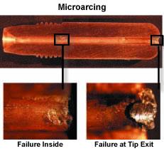 |
| Figure 2 Microarcing can cause the tip to fail prematurely. Courtesy of Tregaskiss, Windsor, Ont. |
Contact Tip Selection
Contact tip selection can make or break an aluminum application. Contact tips can be broken down into two categories: standard and oversized. Every torch manufacturer offers a contact tip for aluminum applications; choosing the correct tip becomes the challenge. A basic understanding of the mechanical advantages and disadvantages of tip sizing can make contact tip selection more effective.
Oversized Contact Tips. Oversized contact tips typically are one wire diameter bigger than the wire being fed. For example, a 0.047-in. aluminum wire will use a 0.052-in. contact tip. They allow the wire to be fed through with less resistance. This decreased resistance reduces the mechanical efficiency of the welding process and increases the chance of microarcing (see Figure 2).
Standard Contact Tips. A standard contact tip typically is the same diameter as the wire. A standard tip increases the sliding friction on the wire, making the welding process more efficient. The increase in friction reduces the chance of microarcing; however, as the wire heats from the welding process, it expands (see Figure 3), causing premature tip failure by jamming the wire inside the tip. The degree of expansion is directly related to the welding output: Higher welding currents will accelerate the expansion process.
 |
| Figure 3 Wire expansion can cause a premature tip failure or jamming of the wire inside the contact tip. Courtesy of The Lincoln Electric Co., Cleveland. |
Users often choose an oversized tip instead of a standard tip because the efficiency disadvantage can be overcome more easily than predicting thermal expansion rates. Thermal expansion is directly related to the welding process; as the welding process is changed, the expansion rates change. Tuning a process to a changing variable never is recommended. Because microarcing is inherent with an oversized tip, it's critical to implement a tip maintenance schedule.
It's good practice to perform a study to determine how many welds can be made before a tip failure occurs. Once a tip replacement frequency is determined, you can implement routine replacement procedures into the production schedule. A maintenance schedule minimizes lost production often associated with fused or failed tips.
Because robotic GMAW of aluminum has some known limitations, you should take care when selecting your robotic package. The wire drive and delivery system is critical to process success.
The drive should be robust and tightly coupled to the robot control architecture, and the delivery system requires little to no line resistance.
The key to success is to understand the process limitations and design a system to overcome them.
Joe Hoffman is a materials joining engineer at FANUC Robotics America Inc., 3900 W. Hamlin Road, Rochester Hills, MI 48309-3253, 800-477-6268, Joe.Hoffman@fanucrobotics.com, www.fanucrobotics.com.


The Welder, formerly known as Practical Welding Today, is a showcase of the real people who make the products we use and work with every day. This magazine has served the welding community in North America well for more than 20 years.
start your free subscription
Easily access valuable industry resources now with full access to the digital edition of The Fabricator.

Easily access valuable industry resources now with full access to the digital edition of The Welder.

Easily access valuable industry resources now with full access to the digital edition of The Tube and Pipe Journal.

Easily access valuable industry resources now with full access to the digital edition of The Fabricator en Español.
Patrick Brunken, VP of Addison Machine Engineering, joins The Fabricator Podcast to talk about the tube and pipe...