Consultant
Cut speed on holes should hover around 60 percent of the speed you use to cut the outside contour of the part. While doing so will create some low-speed dross on the bottom portion of the hole, it will minimize taper in the hole.
Editor’s Note: This is the first article in a two-part series about cut quality in CNC plasma cutting machines. Part I addresses achieving quality when cutting holes. Part II will address dross, edge angularity, warpage, and edge metallurgy.
When it comes to CNC plasma cutting, the same basic questions regarding cut quality always seem to surface. With a little troubleshooting, you can almost always find a resolution to your cut quality problems by selecting the right plasma torch consumables, adjusting your power levels (amperage), and tweaking cut speeds and cut heights.
Hole quality in particular is one of the most frequently discussed topics in regards to CNC plasma cutting. Holes that are out-of-round or that have taper (the top of the hole is larger than the bottom) are common problems in many shops.
If you are having trouble achieving the desired quality when cutting holes, there are tips and techniques that might help. Keep in mind that not all plasma machines are the same. The process capability varies considerably between manufacturers.
This variation is especially pronounced with light industrial or entry-level tables. Any table you consider should include a fully functional height control and good CAM (postprocessing) software. In addition, you should carefully consider the table’s acceleration capabilities and ensure the maximum cut speed is high enough for your needs.
A variety of different requirements exist for hole quality on steel parts. Usually holes are used to bolt finished assemblies together. The rule of thumb for the best hole quality when performing the cut with either an air plasma or oxygen-based high-definition system is that the hole diameter should be no smaller than the plate thickness.
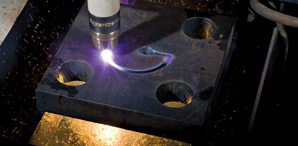
If you attempt to cut a hole with a diameter that is smaller than that of the plate thickness, you’ll end up with distortion and excess taper. A hole that is cut properly using an air plasma system will be round (top and bottom) and will include some natural taper because of the lagging arc angle from the plasma cutting jet.
Let’s look at seven ways you can improve hole cut quality.
Also, make sure to abide by the manufacturer’s recommendations for pierce delay time. These two parameters are critical in decreasing the amount of molten metal blowback on the torch shield and nozzle orifice. Piercing too close or moving the torch before the pierce is complete will cause orifice damage that will alter cut quality.
A good height control will accurately find the surface of the material, and then it will retract to pierce height, fire the torch, and remain at the pierce height until the pierce delay timer times out. Then it will index quickly to the cut height, allowing the X and Y machine motion to start its way through the lead-in cut path.
A hole that is cut properly using an air plasma system will be round (top and bottom) and will include some natural taper because of the lagging arc angle from the plasma cutting jet.
This is important for two reasons. First, there usually is a slag puddle on the top of the plate. If this puddle stays on the radius (contour) of the hole, it will cause the plasma arc to waver and create a divot or ding in the hole. Second, a longer lead-in gives the plasma arc time to stabilize because pressure and energy take a while to ramp up. It also allows the height control to index down to cut height before it arrives to the contour of the hole.
Some cutting machines have better motion control in terms of acceleration and mechanical backlash than others, but most will produce excellent holes when lead-in shapes are straight and perpendicular to the hole. Machines that are more sluggish will benefit from radial or curved lead-ins.
Even better (if your CAM software allows for it) is to add an overburn on holes. An overburn is an extension of the hole radius past the 360-degree lead-in kerf for about 0.150 in.
Some software can actually shut off the plasma arc at the lead-in kerf crossing while keeping the motion active. This allows for a smoother end-of-cut transition and a minimal divot at arc-off.
Cut speed on holes should hover around 60 percent of the speed you use to cut the outside contour of the part. While doing so will create some low-speed dross on the bottom portion of the hole, it will minimize taper in the hole.
Some machines and CAM software do this automatically on all holes less than a certain diameter, such as 1.25 in., while other software may need to have the G-code manipulated to achieve this. Either way, cutting too fast will surely increase hole taper.
In holes that are less than 1.25 in. in diameter, it is best to disable arc voltage control and voltage height correction but enable the pierce height and the indexing-to-cut height. The slower speed used for cutting holes will cause the arc voltage height control to move the torch too close to the plate.
Again, some machines and software can automatically freeze height on all holes less than a designated diameter (less than 1.25 in. is recommended). But a cut height that is incorrect will increase taper on holes.
Running the torch over a slag pile that was produced during piercing will affect the roundness of the bottom of the hole. The spray, applied before the cut is made, usually eliminates spatter that can occur when piercing, minimizing arc wobble on holes. While you’re at it, spray a little on the front of the torch to keep spatter off the shield and nozzle.
Do not use spatter dips, but instead use water-based spray. You may be surprised how something so simple can improve cut quality.
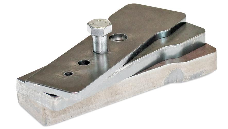
The rule of thumb for the best hole quality when performing the cut with either an air plasma or oxygen-based high-definition system is that the hole diameter should be no smaller than the plate thickness.
This will reduce cut speeds but will give you better results. Use 45-amp shielded consumables for cutting material thicknesses of 0.1875 to 0.375 in., and 65-amp consumables for material thicknesses of 0.375 to 0.625 in. Using higher power levels and consumables will create more taper in holes.
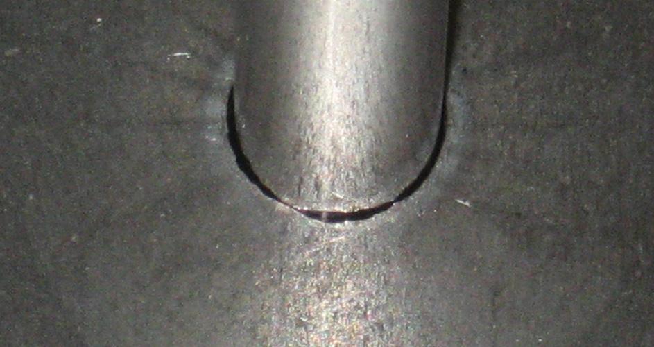
The nozzle and shield orifices must be perfectly round—no nicks, dings, or craters. Inspect the nozzle and shield orifices with a jeweler’s 10x eye loupe. If you find they are not perfect, use these parts for hand cutting or contour cuts that are not as critical.
The orifice shapes the arc, and the arc shapes the part you are cutting. Piercing too close or too wide can damage a nozzle orifice in one pierce. Good-quality consumables that receive regular inspection per the instructions in the operator’s manual are the key to best cut quality.

The Welder, formerly known as Practical Welding Today, is a showcase of the real people who make the products we use and work with every day. This magazine has served the welding community in North America well for more than 20 years.
start your free subscription
Easily access valuable industry resources now with full access to the digital edition of The Fabricator.

Easily access valuable industry resources now with full access to the digital edition of The Welder.

Easily access valuable industry resources now with full access to the digital edition of The Tube and Pipe Journal.

Easily access valuable industry resources now with full access to the digital edition of The Fabricator en Español.
In this episode of The Fabricator Podcast, Caleb Chamberlain, co-founder and CEO of OSH Cut, discusses his company’s...