


Senior Editor
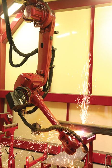
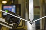
Figure 1
This robotic plasma cutting operation cuts rectangular tube. The cut path, generated with offline programming and simulation, changes from job to job. Photo courtesy of Octopuz Inc.
Robots are no longer a rarity in metal fabrication, even in the smallest job shops. This is true for welding and, more and more, for plasma cutting as well.
Several idiosyncrasies make robotizing plasma cutting a little different. The plasma torch has no wire to touch off the part when using a teach pendant. The torch is bulkier than a wire welding gun, which makes it difficult to maneuver in tight areas. And making a cut isn’t just a matter of going from point A to B, but also from cutting straight to cutting a bevel, slowing down to round a corner, and lowering the current to minimize heat. The variables abound (see Figures 1 and 2).
But according to sources, managing these variables isn’t as arduous as it used to be. Thanks to several significant advances, robotic plasma cutting now can make sense in high-mix, low-volume environments—and in some cases, even for a quantity of one.
Programming a robot via teach pendant can be a chore. Plasma cutting uses no wire, so the programmer goes point by point, using a separate touch-off nozzle probe, or sometimes a laser, to determine the right standoff distance.
Problems like collisions or robot reach issues often arise. When they do, a programmer makes the adjustments manually to each point along the cut path. Things can get even more arduous if the part moves rotationally or linearly during the cutting cycle.
“One of the biggest barriers to [robotic plasma cutting] really boiled down to programming time. To program even a simple cut meant taking a machine out of production,” said David Niewinski, robotics applications manager and designer at OCTOPUZ, a third-party robotic programming software maker in Cambridge, Ont., Canada. “For simple parts it could have been an hour, and for more complex parts, it could take weeks. If that part was going to be run every hour of every day for the next five years, two weeks down was not a huge deal. But if you had custom and one-off parts, that wasn’t reasonable at all. This also applied to welding and really any robotic application.”
Years ago offline programming used to be, in essence, a virtual teach pendant. A technician programmed his way slowly and tediously, point by point. Sure, programming didn’t tie up the robot on the floor, but it took hours or days of engineering time. For a small batch, it usually wasn’t worth the effort.
Today offline programming and simulation packages read exported files directly from 3-D modeling software. As Niewinski explained, “It’s more part-focused instead of robot-focused.”
“Offline robot programming has become much easier to use,” said Jorge Isla, global technology manager, welding and cutting at ABB, Auburn Hills, Mich. “If a technician has exposure to popular 3-D CAD systems, he will probably be able to develop a robot program in no time.”
Like CAM software in the machining world, programming software for robots generates toolpaths offline. Safeguarding, fixtures, the cutting torch, hoses, the power source, and other components all are represented virtually on-screen (see Figure 3). If any object touches another object, the software flags the programmer, who then can correct the problem. The same thing goes for any programmed toolpath that presents problems for the robot. If the programmer makes a change to one or two reference points, the hundreds or thousands of other points in the program use those reference points to make the appropriate adjustments.
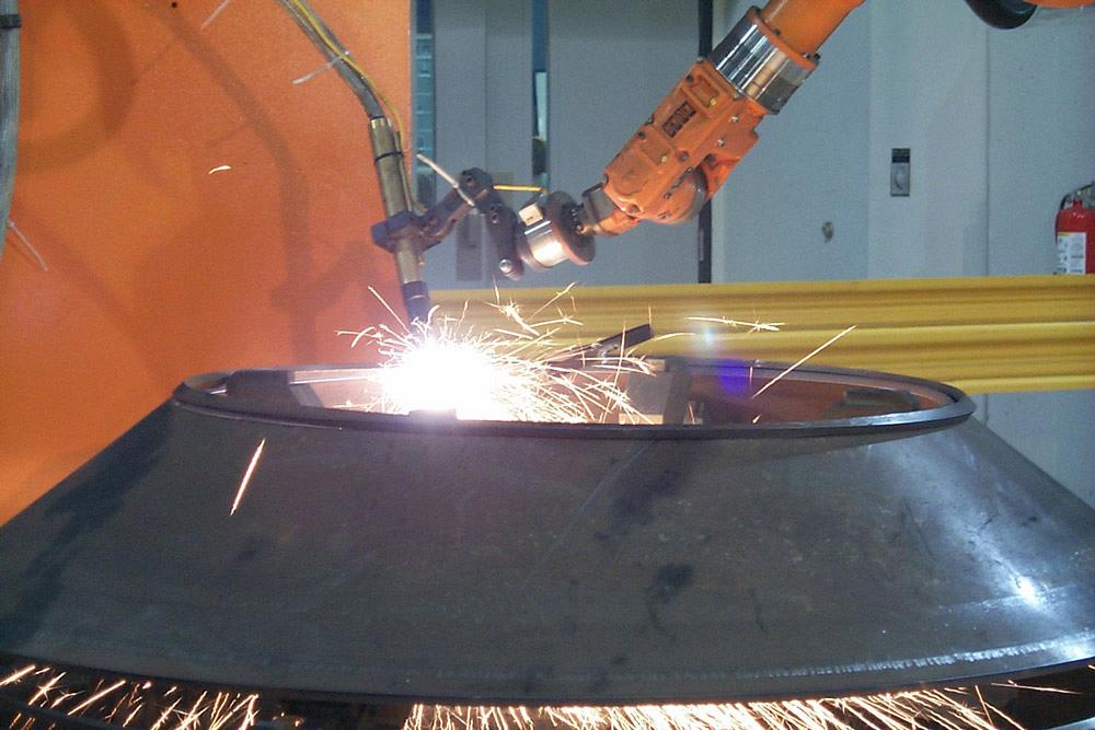
Figure 2
This complex cut on a curved surface was programmed and simulated offline. Photo courtesy of Genesis Systems Group.
As Isla described, the details of offline programming vary with the software being used, but the basic idea behind all of them is to speed programming and catch errors in the virtual space, before a real part reaches the robot cell. This includes not only the linear cut path, but also the angular position of the plasma torch.
“If you see an error, you can delete or move the target [on the toolpath] and move on,” Isla said. ”Or, if you generate the whole path, and you didn’t recognize the error until the robot starts moving in the simulation, you can then go to that target and remove it or move it.”
Offline programming works with a virtual tool center point (TCP), the home base for the robot’s coordinate system. This virtual environment is considered the “perfect world,” but at some point, usually when the robot system is installed, the virtual world has to be calibrated to the actual conditions in the robot cell.
For plasma cutting, some use a touch-off nozzle with a point that’s as long as the standoff distance between the workpiece and torch tip. Screwed on- to the torch body, the touch-off nozzle touches the workpiece. This calibrates the offline programs to their real-world locations.
To cut an entirely new part with a plasma cutting robot, a technician first imports the 3-D CAD file of the finished part into the offline programming software, decides which edges he wants to cut (as well as the pierce points and other cutting parameters), and ensures there are no collision and reach restrictions. He then creates the program and simulation using established fixture component libraries and cutting conditions.
The toolroom builds a flexible fixture with a few precision-mounted hard stops, as well as springs and toggle clamps. This fixture is placed on a base plate and wheeled to a staging area, where the workpiece is clamped in place. (Alternatively, the technician could use a flexible fixturing table with holes, such as a Bluco system.)
Once the robot completes the current job, the technician swaps out the fixture and downloads the new part program via a company network or a USB stick. Pretty soon the robot commences cutting. The whole changeover takes a matter of minutes.
According to sources, many (if not most) applications are accurate enough that they don’t require programming touch-ups at the cell itself. The operator loads the part, brings up the program, and the robot starts cutting.
In some circumstances, an operator may have a situation in which the fixture or part location isn’t repeatable enough to produce a perfect cut every time.
“The physical world is not perfect,” said Isla. “So we [use tactile sensors or other methods] to measure in different locations to know the actual part location.”
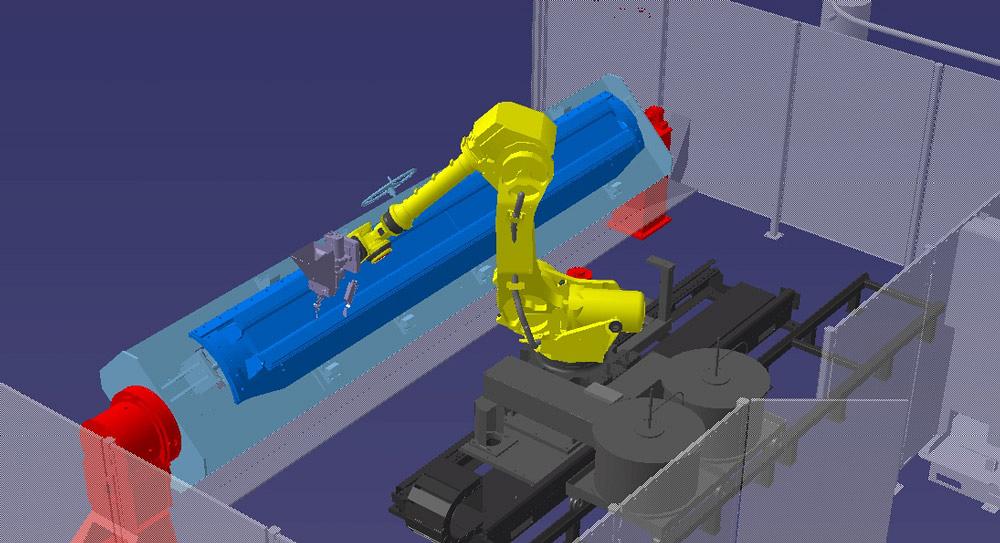
Figure 3
In offline programming and simulation, the entire robot system is simulated, detecting problems before a part reaches the fabrication shop floor. (This shows a welding application, but similar simulations can be done with robotic plasma cutting.) Image courtesy of Genesis Systems Group.
And again, plasma cutting has no wire to probe with to determine the part location. So sometimes the robot swaps out (automatically or with the operator’s help) its plasma head with a touch-sensing head, be it a physical probe or laser. Other times robots use vision systems that take a picture of the part to determine its location.
Sometimes a more basic solution will suffice. “We’ve had people put wire or some kind of extension on the torch itself so they can do touch sensing for plasma cutting,” Niewinski said.
Depending on the application, these part-locating probes may extend perpendicular to the torch body. In this case, both the cutting torch and the probe has its own TCP in the robot program.
Regardless of the method, part-location sensing allows the robot to know where the actual part is and update the program with any changes. This update does not change the torch TCP, only the part’s relationship to the robot. The code adjusts to follow the part’s new position.
Once cutting, the plasma torch still may come across a section in the workpiece that causes the electrical characteristics of the cut to change. Here, like in welding, advances in plasma cutting power supplies have helped.
“The robot can monitor the arc voltage in real time, while it’s cutting, and make adjustments to the torch-to-work distance on-the-fly to maintain the programmed distance and achieve a consistent cut quality,” said Kyle McKearney, project manager at Genesis Systems Group, Davenport, Iowa.
A traditional plasma cutting torch is rather bulky, with a flat end. Now torches with tapered nozzles allow the torch to approach the workpiece at the angle required for cutting bevels (see Figure 4).
“Bevel consumables come down to a point, so you’re now able to tilt the torch on its edge up to plus or minus 45 degrees,” McKearney said, “and still keep the torch at an optimal work distance.”
He added that many torches are now designed in two sections: a main torch body and a detachable lower cartridge that contains all the torch consumables that can be swapped out for different jobs. In many cases, operators can swap out cartridges in less than 30 seconds.
These applications also can incorporate automatic gas-selection consoles that can change the gas mixture depending on what the job demands. The operator works with an interface that shows him various gas “recipes” that also include preflow and postflow settings. The flow rates and other details are already set. All the operator needs to do is choose the gas recipe, and the system takes it from there.
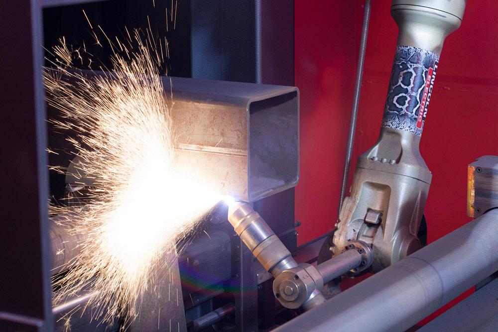
Figure 4
Certain plasma cutting nozzles on robotic systems now have tapers on them to allow for bevel cutting and other applications in which the torch approaches the workpiece at an angle. Photo courtesy of ABB Inc.
Many robot systems can switch out the plasma torch with a welding gun. In some cases, robot cells are outfitted with automatic end effector tool changers. “A robot can automatically switch from a plasma cutting application to a welding application during the same cycle,” McKearney said.
Flexible plastic tubing used to help protect the plumbing (for air- and water-cooled torches) and other dress-out components (which connect the torch and other end-of-arm elements to the rest of the system) also have helped plasma cutting robots tackle a greater variety of jobs.
A fully articulating torch opens up cutting options. Say you have to make a bevel—not a problem, especially if you have a tapered nozzle. This also means the torch is cutting through a greater thickness.
With a robot, you can compensate for this by tilting the torch slightly backward so that the plasma cuts forward. “This allows you to cut faster, and you usually get a cleaner edge,” Niewinski said. If you cut straight down [the beveled edge], your kerf will flare backward relative to the direction of the travel.”This deteriorates the edge quality near the bottom of the cut. Without the ability to tilt the torch, you may need to slow the torch travel significantly to avoid this. Yet the slow travel speed also can introduce excess heat, which causes its own issues.
Some challenges remain in adapting robotic plasma cutting to certain situations. Cutting small circles, about 0.375 inch and less, can be problematic. This has to do with the capability of the robot arm to move in small circles. Here, some type of CNC machine or table might be a better choice.
Best practices in robot operation also need to be followed, of course. This includes electrical grounding. “Grounding is a big deal, because of the high- frequency plasma cutting uses to establish an arc and its effects on the sensitive electronics within the robot,” McKearney said, who added that plasma cutting system manufacturers have basic grounding schemes to use as a starting point. “Each system is different.”
Also, make sure the torch’s zero position is close to the work. Say the workpiece is fixtured below the torch and the torch faces up at the beginning of the program. Here the robot torch needs to flip 180 degrees to access the workpiece at all. Throughout the cutting program, this puts one robot joint (or more) in a position that’s at least 180 degrees from the zero position. For many moves the arm may need to go another 20 degrees or more, putting the joints close to or past their limits of motion.
“If you had pointed the head downward at the beginning,” Niewinski said, “then you could do all of your cutting within 20 degrees of zero, versus within 20 degrees of 180. One of them is close to your limits, and the other is nowhere near.”
Also, workpieces should be positioned far away from where the robot may have trouble calculating its next move. Say the end-of-arm torch can stay steady, but several joints on the arm can move in all directions and still maintain the same torch position. This can happen if the robot reaches directly overhead, or, if the robot is mounted upside down, directly below itself. In this case, the mathematics involve infinite options, which the controller can’t handle. In robotics, this is known as a singularity.
“There’s no way for the robot to calculate which motion is best,” Niewinski said, “though robot controllers are getting better at handling these issues.”
Also, if a robot is installed upside down, perhaps so it has better reach around a workpiece, some robot controllers need to be told that the robot is upside down, because the robot’s movements need to compensate for gravity.
“If the robot doesn’t know which way gravity is exerting force, it doesn’t know how to compensate for it, and so you see accuracy issues,” Niewinski said.
Programmers also must consider how previously cut slugs will evacuate the area. If slugs can become trapped in a certain workpiece, technicians need to find ways to remove it. Fixtures may need to be able to tilt the workpiece a certain way, for instance. For the occasional job, the cutting cycle may need to stop so that the operator can enter the cell and remove slugs.
Fixtures themselves need to be flexible to handle various parts in one or several part families. At the same time, they need to be robust enough to withstand the plasma cutting environment. That environment can be quite dirty. That said, robots aren’t maintenance-free, either. If they aren’t cleaned regularly, plasma dust can get into the seals and other areas of the robot arm.
Other typical best practices in plasma cutting also apply in a robotic cell. Inspect and replace torch components as needed. Also, never fire the torch into the air or keep the torch burning after running a cut off the edge of the workpiece.
As with welding, robotic plasma cutting continues to make more sense in more applications. Fabrication accuracy from upstream processes also helps. This, combined with strategic fixturing, minimizes part geometry variation in the robot cell. In more applications, robots don’t need to probe and compensate for small changes in part geometry.
It boils down to accurate parts, easier programming, flexible components like quick-change tooling and quickly adjustable gas mixtures, smart fixturing, and smart power supplies that monitor cutting arc conditions. Taking all this together, no longer do you need high volumes of one part, or even one part family, to justify robotic plasma cutting.


The Fabricator is North America's leading magazine for the metal forming and fabricating industry. The magazine delivers the news, technical articles, and case histories that enable fabricators to do their jobs more efficiently. The Fabricator has served the industry since 1970.
start your free subscription
Easily access valuable industry resources now with full access to the digital edition of The Fabricator.

Easily access valuable industry resources now with full access to the digital edition of The Welder.

Easily access valuable industry resources now with full access to the digital edition of The Tube and Pipe Journal.

Easily access valuable industry resources now with full access to the digital edition of The Fabricator en Español.
Cameron Adams of Laser Precision, a contract metal fabricator in the Chicago area, joins the podcast to talk...