


Creative Marketing Director
There is no “one-size-fits-all” process that can produce a quality pipe or tube bend for every application. Tube and pipe bending operations use various methods—including compression bending, roll bending, freeform bending, and (the most common type) rotary draw bending—to achieve the desired result.
Every bend has an inside bend radius, outside bend radius, and centerline radius, or CLR. The CLR is the radius of the neutral axis, where there is no material compression or expansion. And each bending method involves different variables to create the desired product with the required CLR. In compression bending and rotary draw bending, the pipe or tube is formed around a bend die, though each forms the tube around the die in a very different way. In rotary drawing, a mandrel can be inserted inside the tube, a process called mandrel bending, to help prevent defects while the material is being formed around the bend die. Mandrel bending excels when it comes to forming tight radii in thin-walled tubes and pipes. In both compression and rotary draw bending, the size of the bend die determines the workpiece CLR. In roll bending and freeform bending, the CLR is determined not by the tooling’s size, but by how the tooling moves.
No method is better or worse than the other. Each is simply different and best suited for specific applications. Understanding the basic tube bending methods, including their capabilities and limitations, can help you uncover the best and most economical way to achieve a quality bend.
During compression bending, a counter die bends, or compresses, the material around a stationary bend die (see Figure 1). The bend die radius must match the desired radius for the part. No mandrel is inserted inside the tube. Therefore, compression bending can compromise tube roundness, and tight radii cannot be bent.
Compression bending equipment has advanced to include CNCs, and some machines have two heads that can produce two bends simultaneously, cutting production time in half. Dual bending heads are especially suited for (but not limited to) producing symmetrical parts. Handles, furniture, and frames of many varieties are typical applications for this type of bending (see Figure 2).
Compression bending may be right for your part if:
Compression bending is not right for your part if:
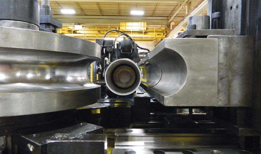
Roll bending is typically used for large-radius bending. Pipe or tube is passed through three rollers configured in a pyramid, and the rollers apply varying amounts of pressure to form the desired CLR. Although the rollers need to match the workpiece outside diameter (OD), they don’t need to conform to the desired radius like a bend die (see Figure 3).
This method is ideal for large-radius bends, coils, and large-radius sweeps. For all of these applications, it would be impractical or simply impossible to build the large bend die for other bending methods. Roll bending may be best if parts require only large radii. Alternatively, if your part requires a CLR smaller than 8 times the pipe or tube OD, roll bending isn’t the right choice.
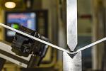
In freeform bending, the pipe or tube is moved continuously through a stationary guide cylinder and then a single die, which moves in the vertical plane according to programmed specifications. The single die must conform to the tube or pipe OD, and the die’s position in relation to the tube emerging from the guide cylinder determines the CLR. To change the CLR, you simply change the die position. This allows you to create complex parts with multiple radii without resorting to multiple bend dies. Still, freeform bending doesn’t use a mandrel, which makes it impossible to achieve tight-radius bends.
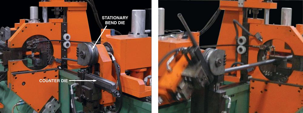
Figure 1
During compression bending, a counter die bends, or compresses, the material around a stationary bend die.
Other methods, such as rotary draw bending, need a straight length between bends to clamp material in place before forming the workpiece over the bend die. Freeform bending, though, does not use any clamping. This not only eliminates the potential for OD marking from the clamps (a problem for cosmetically critical workpieces), but also allows the process to form tubes with no straight lengths between bends (see Figure 4).
Because this process requires minimal tooling, it can produce bends greater than 180 degrees, an impossible feat for methods that need a bend die. Freeform bending is a great process for complex parts requiring multiple radii or no straight lengths between bends, or where cosmetics are important.
In summary, freeform bending may be right for your part if:
Freeform bending is not right for your part if:
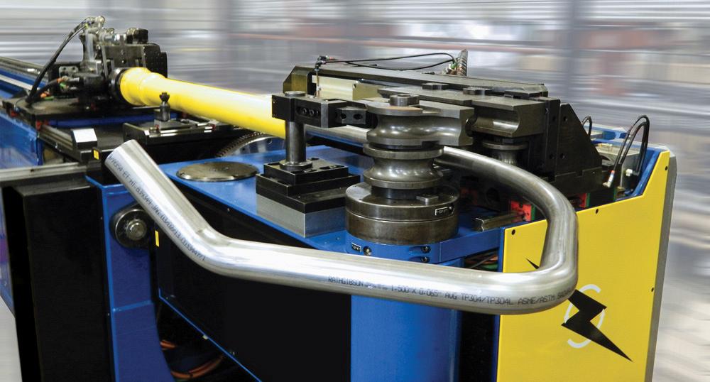
Rotary draw bending is the most common method as it is the most versatile and precise way to create high-quality bends and tight radii down to just 1 or 2 times (1D or 2D) the workpiece OD.
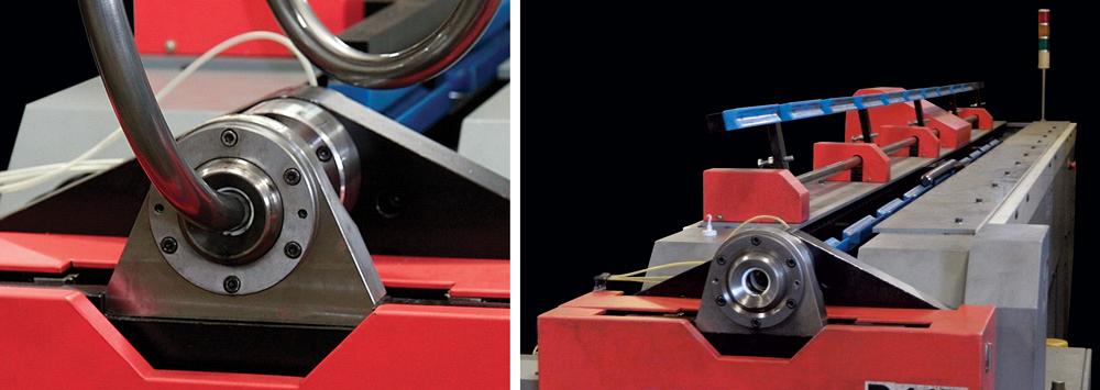
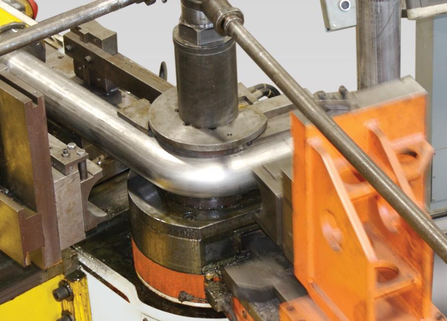
However, rotary draw bending does require more tooling than other methods. It uses die sets that include a bend die, clamp die, and pressure die, along with other components that work in a rotary action. To make the desired bend, the rotary action draws the pipe or tube around the bend die (see Figure 5). Parts can be consistently and accurately produced because the die sets control the process.
Rotary draw bending is the only method that can perform mandrel bending (see Figure 6). This process uses a mandrel, a solid metal tool inserted into the tube before bending, to provide internal support. The mandrel prevents tube defects such as rippling, flattening, and collapse. Using a mandrel also gives maximum control in maintaining tube ovality (roundness), especially in thin-walled tubing, and also makes it possible to achieve tighter CLRs.
Technology and machinery have advanced significantly over the years. Decades ago operators worked with hydraulic machinery, and complex bends required a lot of manual labor. All this added time and labor costs. Using CNC technology and all-electric machinery, operators now can produce those same complex parts much more efficiently.
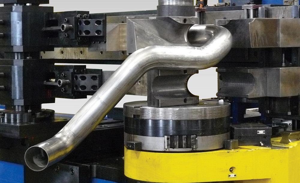
Some modern machines have stackable bend dies, allowing the system to produce parts with multiple bend radii (see Figure 7). Some systems combine rotary draw and roll bending on one machine. This allows parts with both tight-radius and large-radius bends to be produced on one machine. Other machines allow for the bend arm (the part of the machine that actually performs the bend) to flip so it can bend in both a left-hand and right-hand direction. This allows you to produce symmetrical parts on one rotary draw machine.
Rotary draw/mandrel bending may be right for your part if:
Rotary draw/mandrel bending may not be right for you if:
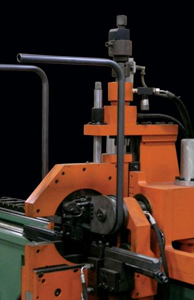
Figure 2
Symmetrical parts like this often are produced using compression bending.
In addition to understanding the bending methods discussed here, it is also important to understand how part design can affect costs. Designing parts for cost-effective tube bending is more involved than it appears. The amount of labor and tooling a job requires dictates much of the costs.
Material costs enter the equation too, but not in the way you might expect. Using thin-walled tube or pipe reduces material costs, but it also might increase your labor costs. That’s because bending thin-wall tubing requires more labor to bend. Technicians need to monitor operations closely to ensure they maintain tube roundness and prevent ripples or wrinkling. In some cases, the additional labor costs outweigh the material savings.
Also consider tooling costs. Traditional mandrel pipe and tube bending requires a bend die built for a specific radius. These dies can range from $2,000 up to $10,000, depending on your pipe and tube size and the radius size. For high-volume jobs, the cost of the bend die might not be an issue, but for small runs it could be critical. Does your design have flexibility for choosing a radius? If so, consult with your tube bending house and find out what radii of bend dies it has in-house. Choosing one of those to design your bend can reduce your tooling costs and shorten lead times.
Next, consider the radius you need. Achieving a CLR less than 1.5 times the tube OD becomes more labor-intensive. If possible, try selecting a CLR 1.5 times the tube OD or greater. For instance, a 4-in.-OD tube bent on a 6-in. CLR, which is 1.5 times the OD, will be less labor-intensive than bending to a 4-in. CLR, which is just 1 times the OD (a 1D bend). Technicians need to fine-tune these critical operations to avoid defects, and this extra time increases the part cost.
Bending parts with more than one bend requires a straight length between the bends. Standard tooling can accommodate parts with a distance between bends of at least 3 times the tube diameter. Parts that have a distance between bends less than 3 times the diameter are possible to produce, but may require special tooling, and this in turn increases tooling charges. An exception to this rule would be if you’re using freeform bending, which creates the bend in a different way.
Finally, keep dimensional tolerances only as tight as necessary. It’s common to design a “safety buffer” when specifying tolerances. Know, however, that tighter tolerances can make the project much more labor-intensive and possibly increase your costs. Be sure to consult with your bending house to find out what bending tolerances can be held while meeting your requirements and without unnecessarily increasing your costs.
Even though pipe and tube bending technology has evolved significantly over the years, the variables remain the same: the OD, wall thickness, geometry of the designed part (simple or complex bends), potential machine interference, and more. Considering these variables from the start and knowing the capabilities of each bending process will help guide you in obtaining a quality bent part.
Images courtesy of Sharpe Products.

The Fabricator is North America's leading magazine for the metal forming and fabricating industry. The magazine delivers the news, technical articles, and case histories that enable fabricators to do their jobs more efficiently. The Fabricator has served the industry since 1970.
start your free subscription
Easily access valuable industry resources now with full access to the digital edition of The Fabricator.

Easily access valuable industry resources now with full access to the digital edition of The Welder.

Easily access valuable industry resources now with full access to the digital edition of The Tube and Pipe Journal.

Easily access valuable industry resources now with full access to the digital edition of The Fabricator en Español.
Cameron Adams of Laser Precision, a contract metal fabricator in the Chicago area, joins the podcast to talk...


