


Structural beam welding automation, no programming required
Say goodbye to the teach pendant
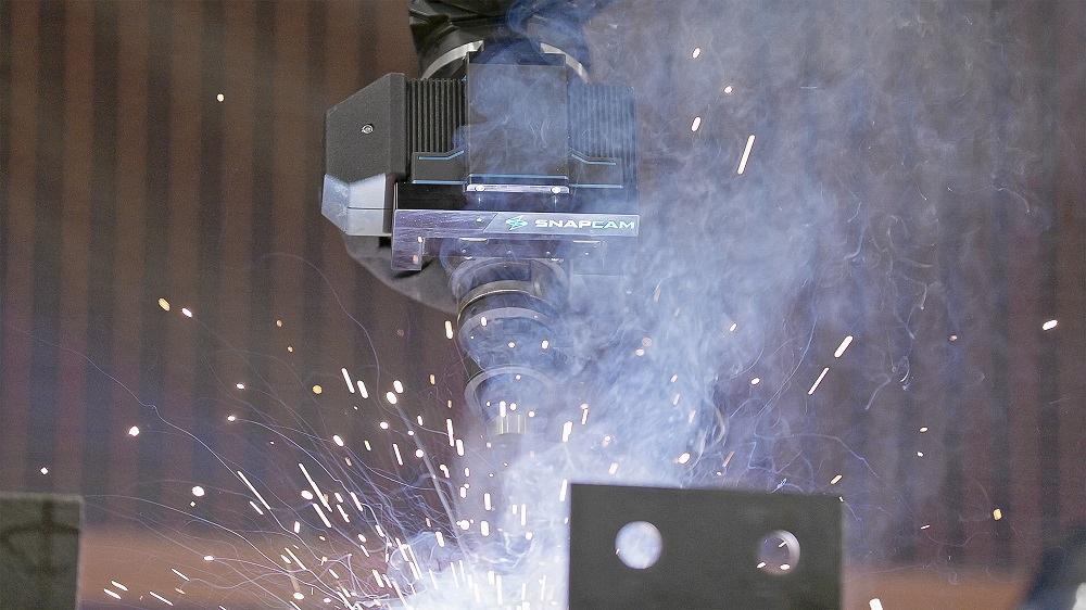
A welding robot reads model information from detailing software and, with a 3D camera, compares it to the structural beam in front of it. It makes adjustments and commences welding, no programming or touch-ups required. Images: AGT Robotics
Editor’s Note: This article had been adapted from “Benefits of adaptive robotics for the metallic industry,” by Louis Dicaire, general manager, and Denis Dumas, marketing and sales director, AGT Robotics, presented at FABTECH 2018 in Atlanta and updated in 2024.
Walk the structural fab shop floor, and you might see some impressive automation, especially at the primary cutting process. The advanced machines drill holes, cope, even scribe layout marks, then cut beams to length. After that, the beams flow to an area that stands in stark contrast to the automation upstream: manual welding stations.
When structural fabricators talk of automation, the skilled labor shortage usually enters the conversation. Problem is, the most efficient and effective automaton usually eliminates only repetitive tasks. And for technologies like welding robots, “repetitive” has traditionally meant “identical,” not “similar.” Welders in structural fabrication might work all day on very similar, but still distinct, jobs—a different size beam with unique coping; flanges that need be attached at certain orientations. Historically, this has created major hurdles to robotic welding. Again, why spend so much time with a teach pendent when welders can just strike an arc?
All this has changed in the last few years, thanks to recent advances in welding automation, especially when it comes to programming. The capabilities of fully automated welding robot programming have continued to grow, as has vision and sensing technology. In short, the industry has come a long way from the teach pendant.
Levels of Robot Programming
Take a step back and look at all the available robot programming technologies, you see characteristics that can be grouped into certain tiers, or levels. The first two continue to dominate the industry; the third level continues to grow; the fourth level is just emerging.
Level 1: Manual Programming. In this scenario, the technician, usually using a teach pendant, programs each path a robot takes. That is, the person must teach the system where to weld, what to weld, and how to weld. Such programming can take hours and require a certain number of identical (not just similar) parts. This legacy process has kept most high-product-mix work away from the robot. And in truth, it’s why robots aren’t yet pervasive, except in the highest-volume manufacturing environments.
Level 2: Assisted Programming. In this scenario, a technician must program each path a robot takes. The programming platform might give some assistance and employ new interfaces, like tablets, or give the operator the ability to physically move the robot (or cobot) arm to different points along the weld path. But it still can take significant time, and it requires the technician to choose and review where the robot welds, what it welds, and how.
Level 3: Offline Programming. This automates the programming of some robot paths. That said, the technician still needs to do some level of manual programing (or “touching up”), since the digital model usually differs from the real part that’s fixtured in the weld cell. Here, the programming method handles most of where to weld, some of how to weld (suggesting certain weave patterns and other techniques), and a little of what to weld—but again, the “what” (the actual part in front of the robot) can differ from the digital 3D model, and a technician needs to account for those differences.
Level 4: Autonomous Offline Programming. Here, technology retrieves 3D information from a drawing and automatically generates the weld seams. It generates all the program points necessary for the welding tool and automatically determines the correct welding procedure to be applied. It also defines all robot movements (without collisions) and plans the sequence of all operations that the robot will perform. Representing the current state of the art, this method tells the robot where, what, and how to weld, all with minimal human intervention.
Whatever level a fabricator is at, managers still need to look at the overall time robotic welding requires. This includes programming, of course, but it also includes tacking, part positioning, and the amount of time between when a part is fixtured and when welding commences. In some manufacturing environments, if a robot spends too much time scanning a workpiece before initiating a weld, throughput can suffer.
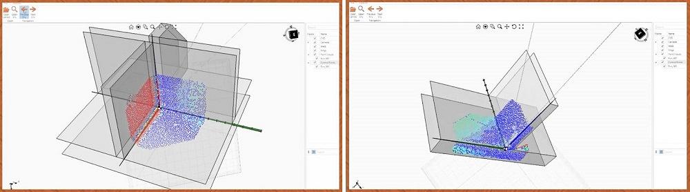
Today, 3D cameras can snap several pictures of the weld area. The robot can compare the joint position and thickness properties to the digital file, make the necessary adjustments, and commence welding.
Why the Teach Pendant Still Dominates
Visit a highly automated weld shop, and you’ll likely find most robots being programmed with a teach pendant, even if the shop has a good 3D model that incorporates welding information. The question is—why? Offline programming and simulation for welding robots have been around for years. Moving all the programming away from the shop floor would seemingly make automated welding effective even for high-product-mix operations.
Moreover, as anyone who’s been to a recent FABTECH probably knows, innovation in welding robot programming has accelerated. Welders now work with tablets to choose weld “recipes” to program the robot (or cobot) and initiate the weld cycle within minutes. In some setups, operators physically move the robot arm from point to point. And with computing power and the ever-advancing algorithms behind artificial intelligence and machine learning, the pace of innovation isn’t likely to slow any time soon.
With so many programming options, why does the teach pendant still dominate? It has to do with time, the inertia of legacy technology, standardization, and available resources. The vast majority of welding robots today can be programmed with a teach pendant. Shifting to an alternative on-the-floor programming method can make sense, with the right robot cell technology, but the operation still requires people to spend precious time programing the robot at the cell. And when a robot is being taught, it isn’t producing parts.
What about offline programming (Level 3)? First, the best programmers have welding experience, and welding experience is tough to find. Shops with just one or a handful of people programming and simulating a multitude of robots offline can experience a programming bottleneck.
Second, as stated previously, reality always differs slightly from the 3D model. The person loading the cell with a new job often has to touch up the program to account for variances. Time spent touching up can add up, too. Since a touch-up is already necessary, why not just teach-in the weld program from scratch to begin with? Or, as many structural fabricators ask, why not have welders weld manually? Welding automation just doesn’t seem to be worth the trouble.
Why is it such a trouble? It has to do with the nature of robot programming. Considering the industry’s most recent advancements, the nature of programming is set to change dramatically. The latest systems (now at Level 4) utilize 3D cameras that can literally “look” at a beam at several points, compare what they see to the 3D model from the detailing software, calculate the necessary adjustments on the fly, then commence welding. They detect the position of T-joints, lap joints, and other geometries, and they can do this in less time than previous iterations of the technology.
The robot also makes in-process adjustments to account for real-world conditions. For instance, if the robot weaves within the joint geometry, the closer the electrode tip gets to the edge of the groove (the standoff distance), the higher the current will be. If the current variation goes outside a certain range, the robot knows the joint position has moved and can make the appropriate adjustments.
The approach goes a step beyond parametric programming, where a program is built around specific parameters—like minimum and maximum length of a weld—and from that, the program can adjust quickly to the work in front of it. In contrast, fully automated programming can work with a wide group of parts and uses advanced algorithms to build a program. It doesn’t simply vary a program around specific parameters like length, height, width, depth, or another dimension.
This effectively automates both the weld programming and the act of touching up at the weld cell. A technician opens the file, selects the parts, and launches automatic programming and simulation. That then is sent to the control, where the operator loads the part, selects the program, and walks away.
Welding With Context
The ability for a robot to “look and then weld” is just a small piece of the productivity puzzle, especially in structural fabrication. Scrapping a beam isn’t cheap, and if it’s scrapped in welding, all the value that went into it during upstream processes goes out the window. Beams need to be cut, fitted, fed, handled, and positioned for optimal weld access.
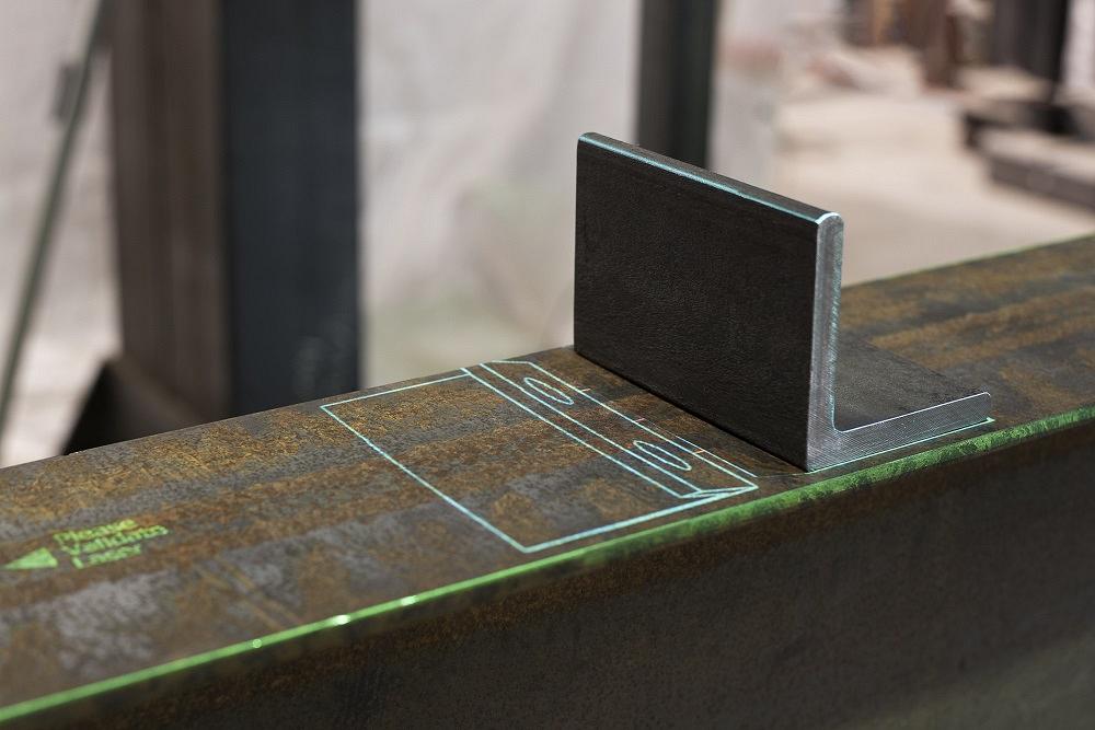
An overhead laser projects layout marks at the fitting station. The system draws directly from a digital file from detailing software.
Imagine a highly automated beam processing center at a structural fabricator. Pieces are loaded, the machine reads information from the detailing software, and the operation commences. Everything flows with little operator intervention. The beam then reaches the fitting station. Someone might measure and place layout marks by hand—and then make a measurement or locating error (locating from the edge instead of a critical feature, for example), or perhaps misread a drawing. Rework ensues.
The structural fabricator has, in effect, two “islands of automation” amid a sea of (sometimes unpredictable) manual operation. Another way to look it at: The flow breaks the “digital thread.” The automation is fed files directly from 3D detailing software, yet layout marks are still being made with a measuring tape and marker.
Scribing at the beam processing center can help fix this, yet scribing complex layout marks (an outline of a fitted component, for example) adds cycle time. Anything that hinders throughput on an upstream process, and especially a shop’s primary cutting operation, can snowball into more problems downstream. So, programmers might decide to minimize the scribing, with a few subtle marks instead of, say, a complete outline of the part to be fitted. Instead, they might reserve marking operations to scribing part identification.
Alternatively, the operation might choose to employ a fitting station with layout marks projected by an overhead laser. This strategy has several advantages. First, it eliminates the need for manual layout or the need to tie up a beam processing line with excessive amounts of scribing. Second, since the projection technology draws directly from 3D models, it maintains that digital thread throughout the shop routing.
From there, the beam flows directly to a cell with a positioner that rotates it and a welding robot that can access all joints. And that flexible positioner is critical. Its design needs to be flexible enough to accept a variety of structural beams and other shapes, and it needs to be designed to allow full weld access, including 360 degrees of rotation. As anyone who works in large-workpiece fabrication knows, structural or otherwise, an operation can spend more time moving jobs than actually fabricating them.
At the robotic weld cell, a camera mounted on the robot quickly scans two points, performs the digital-model-versus-reality adjustments, and commences welding. There’s no manual programming, on the shop floor or offline; no arduous repositioning of the beam or structural shape; no mistakes in fitting; no constraint in layout; no miscommunication; and an unbroken digital thread throughout.
More significant, though, is how such automation can now help structural fabricators optimize the entire cut-fit-weld cycle. More reliable flow and minimal to no setup allow planners to reduce work-in-process (WIP) between steps. Less WIP equates to shorter lead time and greater throughput—even in a highly variable environment like structural fabrication, where unexpected changes in the construction value chain can force fabricators to turn on a dime.
The Big Picture
Automated programming in welding is sure to evolve and eventually become par for the course in the industry. A fabricator’s customers don’t pay for robot programming, and they don’t pay for repositioning the work. They’re paying for fabricated metal shipped at the right time, quality, and quantity.
Such automation could help fabricators scale in new ways. Manual welders would continue to work on a wide variety of parts, but not repetitious work. Every day they come into work, they’ll see something new.
Meanwhile, a shop’s welding robots could churn out large volumes of identical parts, as they always have, but systems with automated programming could process a broad group of related products. Again, deciding what to automate requires holistic thinking. A flexible weld cell with an automated program needs to work within a system, including efficient weld prep, flexible fixturing, and positioning.
Over time, as technology evolves, that broad group of products could expand to include even more variety and even greater autonomous operation. One day, an even higher, completely autonomous level of robot programming may well become commonplace. The robot will “look” at the job in front of it and commence welding—without any human intervention whatsoever.
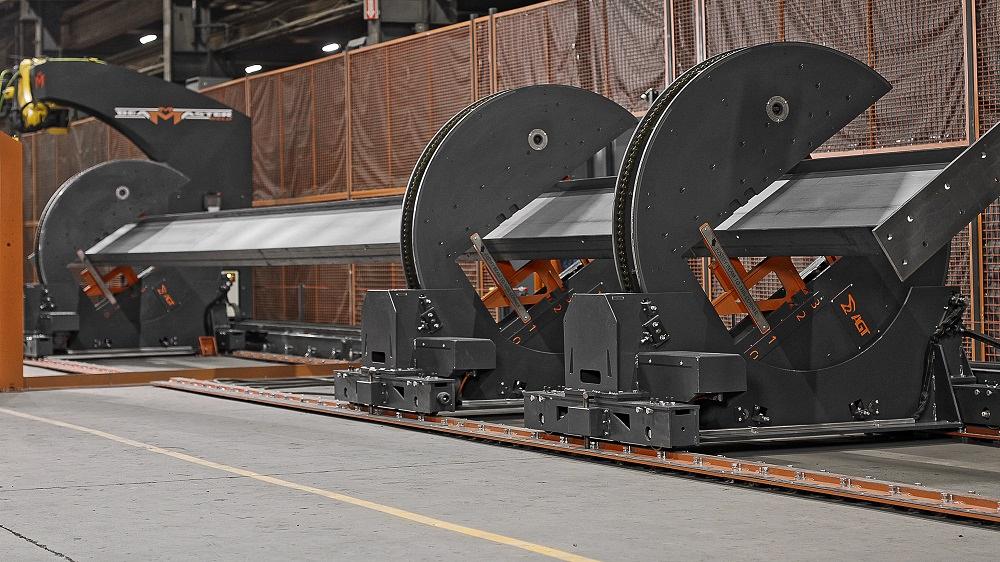
A positioner rotates a beam so the welding robot can access all joints in one setup.
About the Publication
subscribe now

The Fabricator is North America's leading magazine for the metal forming and fabricating industry. The magazine delivers the news, technical articles, and case histories that enable fabricators to do their jobs more efficiently. The Fabricator has served the industry since 1970.
start your free subscription- Stay connected from anywhere

Easily access valuable industry resources now with full access to the digital edition of The Fabricator.

Easily access valuable industry resources now with full access to the digital edition of The Welder.

Easily access valuable industry resources now with full access to the digital edition of The Tube and Pipe Journal.

Easily access valuable industry resources now with full access to the digital edition of The Fabricator en Español.
- Podcasting

In this episode of The Fabricator Podcast, Caleb Chamberlain, co-founder and CEO of OSH Cut, discusses his company’s...
- Trending Articles
1
Tips for creating sheet metal tubes with perforations

2
Supporting the metal fabricating industry through FMA

3
JM Steel triples capacity for solar energy projects at Pennsylvania facility

4
Fabricating favorite childhood memories

5
Omco Solar opens second Alabama manufacturing facility
