


Senior Editor
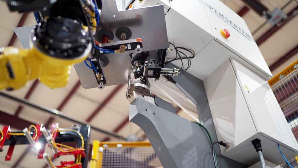
A robot positions a workpiece for a hardware insertion system set up to deliver and insert several different kinds of hardware.
Hardware insertion isn’t the most glamorous of processes in sheet metal fabrication, but it still has to be done right. Nothing can be more infuriating than rework or scrap caused by hardware problems, be it missing or stripped hardware or the wrong fastener altogether.
Fabricators tackle the problem using a combination of strategies. After some 5S, a fastener department might incorporate bins complete with picture-based labels and establish a reordering system, be it in-house or through vendor-managed inventory, so the department never runs out of the hardware it needs.
The shop might errorproof the process through product design tweaks (does the piece really need all these different kinds of hardware?) and perhaps establish product families and value streams to limit the variety of parts that flow through certain hardware cells. It might even eliminate hardware insertion as a department and integrate insertion presses next to other processes, especially when it aids access to holes. An operator might insert fasteners, perform a few bends on a press brake, then pivot again to insert remaining hardware.
The combination of press brakes and hardware insertion can be effective, especially if a cell is designed around a part family or specific range of part geometries. At some point automation becomes a viable option. But what is that point, exactly? To answer this question, The FABRICATOR spoke with Ryan Smallfoot, integration supervisor at Acieta, Council Bluffs, Iowa.
He explained that a complex part mix isn’t necessarily a barrier. Some robotic cells can produce one different part after another. But the process does need to be repeatable. A typical robot has repeatability far more accurate than most sheet metal applications require. But sheets can still stick to one another. A sheet can slip, perhaps not sit exactly flat on the fastener press’s anvil. Hardware feed errors are a possibility too. Some issues can be eliminated entirely, others only minimized. Regardless, the more process variables a fabricator can engineer out of the equation, the better.
Building an automation cell starts with defining what exactly will flow through it. Smallfoot described one application in which a seemingly infinite variety of sheet metal pieces flowed through a robot cell involving both hardware insertion and press brake forming. No one spent hours with a teach pendant in a robot cell, and the company didn’t have an army of programmers running offline simulations.
Instead, parametric programming played a key role. The parts infinitely varied, but only in defined parameters. When a part geometry changed in a certain defined dimension, robot motion adjusted automatically to accommodate.
Smallfoot clarified that automated cells can handle a variety of parts even without parametric programming. The only physical restraints involve the ability of the robot’s end-of-arm tooling to grasp and manipulate the parts through the operations: grasping the blank, squaring (orientation), hardware insertion, bending, and stacking.
Offline simulation makes the programming of new parts very efficient; a technician might use the teach pendant only for some final tweaking. Regardless, shops need to factor in programming, be it performed offline or online.
Today’s offline programming and simulation are powerful tools, especially when it comes to the robot’s end-of-arm tooling design and collision avoidance. For hardware insertion, for instance, it’s often necessary for the robot’s end-of-arm tooling to stay clear of hardware feeding tubes and other components near the back frame of the press, behind the anvil.
A robot gripper holds a blank steady as hardware is inserted.
Smallfoot added that this depends on the hardware machine’s setup in the cell. Regardless, the robot path must consider the potential for collisions. The clearer the robot path can be—far away from any potential collision points—the better. Integral to all this is the design of the end-of-arm tooling. The better the tooling design, the more collision-free paths the robot can take getting in and around the anvil and the turret of the insertion machine.
End-of-arm tooling will govern part size limits. But as Smallfoot explained, alternative approaches, verified through simulation, could open the door for certain parts that might be too small to handle otherwise. For instance, a blank might incorporate several small parts tabbed together. A robot with the correct end-of-arm tool could carry this blank through hardware insertion and even forming on the press brake, bending multiple pieces all at once. Sure, the pieces would need to be broken apart after forming, but doing so might be faster than having to insert hardware and form all of those small pieces by hand.
Programming must ensure the operation remains as simple and efficient as possible for a given part mix. To illustrate, Smallfoot described the challenges of one hardware insertion cell regarding tonnage settings of the insertion press.
Excessive tonnage problems sometimes occurred because of the hole geometry itself—specifically, a burr on the inside diameter. To make hardware insertion more consistent, the laser was reprogrammed to cut a tiny divot at the hole’s lead-out point. This ensured hardware could be inserted without excessive tonnage.
Occasionally the piece would not be exactly level sitting on the anvil, which also meant that the press needed to exert more tonnage to insert the hardware. What caused this positioning error, exactly? The robot itself is extremely accurate, but other variables came into play, including the part geometry and the effects of inertia and gravity. The ever-so-slight inconsistency sometimes caused the machine to exert excessive force and fault-out.
In manual operations, this wouldn’t be a major concern. It’s welcomed, in fact, because the fault-out is a safety set point designed to prevent the machine from bottoming out and producing a bad part. If the machine faults out, the operator simply reorients the piece, reinitiates the cycle, and continues on.
A conventional robot can’t do this. That said, the press’s original tonnage window was designed to accommodate all applications the press would handle. For a certain application’s insertion requirements, though, the press still could exert a little more tonnage, and the self-clinching fastener still could be inserted well within spec.
So for this application, Smallfoot said that the team worked with the hardware press OEM on software updates that would widen the tonnage window ever so slightly. He added that this might not apply to every automated hardware cell; it all depends on the application requirements. All the same, the example does bring to light the part location challenges that can arise.
It also points to the trade-offs that occur when designing an automated cell. Modern robot arms are very repeatable, often ±0.002 in., but the robot itself is just part of the equation. “The robots are very accurate,” Smallfoot explained. “But you really need a good squaring table so you can qualify the piece, so you know exactly where the corner is. And from that point, you know exactly where your end-of-arm tool is on the piece itself.”
Considering the earlier application, if hole location is a problem, then why can’t the robot simply place the piece in a fixture that secures the part over the hardware press anvil? This could work, theoretically, if the fixture could accommodate all the pieces in a given part mix.
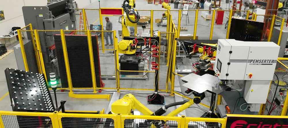
In this cell, a robot aligns a workpiece, presents the piece for hardware insertion, then transfers the work to the adjacent automated bending cell.
But then comes the issue of cycle time. As Smallfoot explained, after the alignment operation at the squaring table, or alignment stand, when the end-of-arm tooling releases the part, it must regrasp the part and sometimes, depending on the circumstances, return to the squaring table and realign the part. Otherwise, the robot is effectively operating blind.
As Smallfoot explained, adding a fixture to hardware insertion is an option. If the fixture is made to tight tolerances, it can be used as an alignment stand, so the robot might not need to return to the squaring table every time it releases and regrasps a part. Regardless, releasing and repicking the piece from that fixture does add cycle time, which can be problematic.
In most cases, simplest is best. And in the application Smallfoot described, a software change that widened the tonnage window slightly was the simplest approach, no fixturing or other complications required.
Simplicity also factors into job sequencing. For instance, say a part has certain hardware locations that create forming challenges. In a manual cell, an operator might insert hardware, turn to the press brake to create a few bends, insert more hardware, then return to create the final bends. Inserting the hardware in this sequence might eliminate forming issues, especially when hardware is located near bend lines.
But as Smallfoot explained, this might not be practical in a robotic setup. Yes, a robot theoretically could carry a part back and forth between bending and hardware insertion, but it does add complexity. Depending on the part and how it’s manipulated, the robot might need to make one or more additional stops at the alignment stand, and its end-of-arm tooling would need to be able to position the partially formed part in the insertion press. This also could require an end-of-arm tool change, introducing even more complexity. The robot theoretically could do it all, but in all likelihood a human operator could do it faster.
A better automation strategy would start with part design. Does the hardware need to be so close to bend lines? If so, can the forming operation use punches in the brake with reliefs that can accommodate the inserted hardware? If this is the case, then a robot could carry the piece from hardware insertion and then directly on to bending.
Smallfoot added that “you can never say never” when it comes to automation. But in many cases, the less complex the robot path, the faster the cycle time, and the more efficient the automation cell can be.
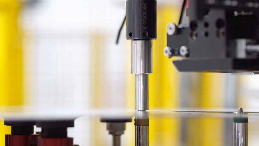
Not everything in a robotic hardware insertion operation needs to go absolutely perfectly. Robotic automation can be programmed to adapt and retry. For instance, Smallfoot described a hardware insertion operation that occasionally faulted out because of a vacuum failure. Hardware was fed from one of several bowl feeders. The hardware traveled down a flexible tube onto a shuttle by the ram of the machine. The shuttle then presented the hardware to the ram. As the ram’s vacuum initiated, the shuttle’s fingers holding the hardware opened, and the hardware was sucked and secured in place inside the ram body. With the ram body on the anvil, the machine cycled and inserted the self-clinching fastener into the sheet metal.
Sometimes, though, that vacuum would fail. “The machine itself would tell us if it faulted,” Smallfoot explained, “and depending on the fault, we would tell it to retry.” He added that for the vast majority of such faults (which themselves were a rarity), simply instructing the press to retry solved the problem.
In most cases, automation cells can use conventional self-clinching fasteners—that is, the same ones that would be used in manual operations. “Though I do know that some companies that make fasteners will manufacture them to customer specs,” Smallfoot said, “so you could build features into the fastener that could make robotic insertion easier.” He added that this could include special lead-ins and other location aids. That said, Smallfoot said that custom hardware isn’t absolutely necessary for most applications.
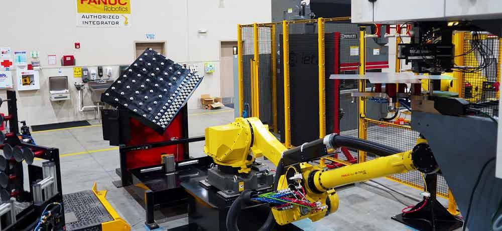
After presenting the part to the alignment station (in the background), a robot presents it to a hardware insertion press. After insertion, the blank is transferred directly to an automated bending operation.
Anvil settings do need to be optimized to fit around the fastener diameter snugly, but not too snugly. “You want the anvil tight enough so that it can locate and insert the fastener,” Smallfoot explained, “but not so tight that you have to force [the fastener] onto the anvil. It should just slip over the top.”
A person still must feed hardware into the bowls, and, of course, the right fastener needs to go inside the right bowl. Many fabricators are all too familiar with the frustration of rework or (even worse) customer returns due to hardware errors.
Here’s where errorproofing comes into play. Smallfoot described a recent hardware application that used two types, one with internal threads and the other with external threads. Outside the cell, the bowl feeders could be replenished without stopping the system. Sensors within the bowl feeders would trigger alarms that notified personnel when they needed to be replenished.
“And the bowl feeders were clearly marked which ones were which,” he explained, adding that even if an operator mistakenly added the wrong hardware to the bowl, the system would stop because the hardware simply wouldn’t fit. “The holes in the parts are different sizes,” he said. “So if you do get hardware in the wrong bowl, the machine itself will fault out because it will either read a high tonnage trying to insert a larger fastener in a smaller hole, or read no tonnage whatsoever when trying to put a smaller fastener in a larger hole.”
For jobs that require quality checks at specific intervals, an automated cell can accommodate. As Smallfoot explained, a cell can be programmed to produce a certain number of parts and then, at specified intervals, place parts in a location where inspection personnel can access them without stopping the automation.
Process monitoring options abound as well. “On a robot, you can track whatever the fault is,” Smallfoot said, adding that certain faults can even trigger emails or other notifications to nearby technicians. Depending on the nature and severity of the fault, this could be when the fault happens or at certain intervals.
Process monitoring capabilities of machines the robot interacts with, including the press brake and hardware press, will depend on the machine in the cell. “As long as the machine gives a description of what the fault is, we can keep a log of that as well,” Smallfoot said. He added that those logs might not include the specific part the cell was fabricating, but it will include the time the fault occurred.
Most thin-gauge sheet metal automation cells do not use robots with magnetic end-of-arm tooling; the magnetic field extends too deep, and the robot picks multiple blanks at once. Suction cups don’t have this problem. And modern suction systems can be designed to handle some challenging geometries, even those with multiple interior cutouts, embosses, and other forms.
“The cups are designed around the features of the part, whether they’re louvers or windows or holes,” Smallfoot said. “Cup placement is important. And you can run multiple vacuum zones. Even if you have a few cups that are in the middle of the gripper that grasp over a hole, the cups to the outside are still drawing vacuum.”
The suction cups might grip securely, but they can’t always prevent double-picking. The cell must incorporate technology to ensure the robot picks up only one piece at a time. As Smallfoot explained, “Many cells use a laser scanning device that can check the material thickness. It’s very quick.”
Speed is critical. If double-picking is detected, a system can use an air knife or other device to separate the sheets. But in many cases, it’s easier and faster to move the double-picked blanks to a reject area, then repick a fresh blank. Those rejected blanks then can be added to the next batch. Speed is also critical at the end of the cell, where pieces can be stacked, placed onto a conveyor, or otherwise carried downstream.
That final step—sending the part onward downstream—is really what effective automation is all about, whether it involves hardware insertion, forming, or anything else. After all, a part isn’t really “finished” with a manufacturing operation until the next operation can do something with it. With the right variables addressed, that’s just what a well-designed robotic cell should accomplish.


The Fabricator is North America's leading magazine for the metal forming and fabricating industry. The magazine delivers the news, technical articles, and case histories that enable fabricators to do their jobs more efficiently. The Fabricator has served the industry since 1970.
start your free subscription
Easily access valuable industry resources now with full access to the digital edition of The Fabricator.

Easily access valuable industry resources now with full access to the digital edition of The Welder.

Easily access valuable industry resources now with full access to the digital edition of The Tube and Pipe Journal.

Easily access valuable industry resources now with full access to the digital edition of The Fabricator en Español.
In this episode of The Fabricator Podcast, Caleb Chamberlain, co-founder and CEO of OSH Cut, discusses his company’s...


