Contributing Writer
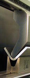
This heavy-duty gooseneck punch with an acute-angle 1V die provides the ability to overbend material to compensate for springback.
Since the early 1980s, sheet metal fabricators have, for the most part, followed a pretty basic set of rules to air-bend mild steel. To determine the appropriate die opening to bend 0.5-inch-thick (12.7-mm) and thinner materials, you simply multiplied the material thickness times 8. To calculate the resulting inside radius, you either multiplied the width of the die opening times 16 percent, or divided it by 6. And one punch with a 0.031-in. (0.8-mm) tip radius could bend nearly anything from 20- to 12-gauge mild steel.
Bending steel plate pretty much meant following those same set of rules, except that you had to use punches with larger tip radii, and when the material thickness exceeded 0.5 in., you would multiply the material thickness times 10 to determine the correct minimal die opening.
Several new breeds of high-strength steel have arrived that bring with them a host of new opportunities. However, these new breeds also bring with them special challenges not common to bending mild steel, and with them, the need for new tools and new rules for proper bending, because the traditional rules for determining minimum bend radius, minimum punch radius, die opening, bending force, and tooling requirements do not always apply.
So what purposes do these new breeds of high-strength steel (HSS) serve? Today's new, stronger steels can reduce part weight, increase part strength, extend part life, improve fatigue and crash performance, and resist abrasion.
Some HSSs, such as Domex®, are designed to reduce the weight of heavy vehicles, trailers, cranes, and containers.
Construction-grade HSS is engineered to reduce the weight and increase the lifting capacity in applications such as mobile cranes, truck cranes, and trailers. Other HSSs are engineered to increase the useful life of equipment such as excavator buckets and truck beds.
Heavy-construction equipment may be made of HSSs, such as RAEX®, that are designed to provide improved resistance to the abrasive wear caused by soil, rock, crushed aggregate, gravel, coal, and sinter. Feeders and funnels, mining equipment, pruning blades, wood processing equipment, shredder blades, and mixing blades may be constructed of this new type of HSS.
So what are the high-strength steels' unique forming requirements? If you are considering taking on a job that will require you to bend some of these materials, it is advisable to consult with the manufacturer or the technical staff at the steel service center before ordering the first piece of material and to ask the following questions:
What special considerations do I need to take into account?
While all of these questions are very important, you should pay very close attention to the last one, because many special considerations for bending these materials are not common to bending mild steel. If these considerations are ignored, problems could result:
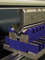
Figure 1 Die shoulder radii should be hardened and very smooth to help to reduce drag during forming.
Simply put, HSS requires high-quality tooling that can withstand the great force generated when bending it.
For example, the tip radius on the punch and the shoulder radii on the dies must be hardened and remain intact. The deeper the hardening zone is, the better, because any breach of the hardened area will lead to a rapid deterioration of the working surfaces, which will decrease accuracy and increase tooling costs.
Wear on the die shoulder radii also increases drag on the material as it flows over the shoulder radii. This significantly increases the amount of force required to bend the material.
Angles Allow Overbends. Make sure the tooling you plan to use has an included angle on both the punch and the die that will provide adequate capacity to overbend the material as necessary to compensate for springback (see lead image). Because HSSs often have high yield strengths, the amount of springback that occurs probably will be greater than the springback that occurs when you bend softer materials such as mild steel and aluminum. If so, your current tooling may not be able to compensate for it.
Heavy Tooling Affects Setup. Setup time is one of the greatest contributors to the cost of bending thick materials in general. This is caused, in part, because handling the large, heavy tooling is difficult. The punches normally have large tip radii and often are composed of a combination of a punch holder and a large-radius insert. The dies normally have large openings and weigh well in excess of 100 pounds, requiring two or more operators and possibly a forklift to load and unload them.
The use of short, modular tooling segments that match properly when installed will make tooling changes faster and safer and, during most setups, will eliminate the need for additional personnel and/or forklifts.
Fewer Tool Changes. Of course, reducing the number of tool changes or eliminating them altogether is even better. This is where an adjustable die can be beneficial, especially one with quick-change capabilities.
Safety. As always, safety must be a very high priority. The rated capacity of the punch and die always should be checked against the amount of force that will be applied during the bending process.
It is also important to remember that a tool with a rated capacity of, say, 12 tons per foot does not mean that you can apply a total of 12 tons of force over any length, regardless of how long or how short the part length or the tooling is. It means that a tool with a rated capacity of 12 tons per ft. is capable of handling a maximum of 1 ton per inch of bending force. Subsequently, if you were to apply 12 tons of bending force over 6-in.-long tooling that is rated at 12 tons per ft., you would be using the tooling at twice its rated capacity. In like manner, a tool with a rated capacity of 24 tons per ft. is rated at 2 tons per in.
Finally, it is always a good idea to use punches with safety clicks or safety tangs, especially with large, heavy punches. This helps reduce the risk of operator injury and damage to the tooling during loading and unloading.
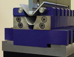
Figure 2 This large-radius punch and punch holder with a quick-change, adjustable die is equipped with rollers on the shoulders that significantly reduce bending force requirements to bend thick material.
Clamping. As mentioned previously, handling large, heavy tooling is one of the greatest contributors to the cost of bending. One of the best ways to reduce setup time is to install a quick-clamping system on the ram of the machine.
This system enables the operator to clamp the punches without the use of cumbersome wrenches and levers. Some of the hydraulic versions also have the ability to clamp, seat, center, and align the tooling with the push of a single button.
Crowning Systems Counter Deflection. The higher amount of bending force required to bend HSS will increase machine deflection. It will also increase the need to compensate for deflection when bending parts that require good accuracy and parts that are typically 8 ft. long or longer. Using the old method of shimming dies is rarely acceptable as it is very time-consuming. Shimming also damages the die holder because the force is partially concentrated over the shims instead of being dissipated over the full load-bearing surface of the lower die holder. This will create the need to have the lower die holder machined periodically, thus adding cost to the overall operation.
The best solution for attacking the problem of machine deflection is to install a crowning system on the bed of the machine. Today's crowning systems come with a host of features that are designed to allow you to tailor them to your specific needs and budget. Features include opposing waves to improve accuracy; localized adjustments to allow the operator to compensate for local wear in the ram and bed of the machine and/or the tooling; drive motors that are interfaced with the control; lower-cost, manual handcranks for the adjustment of the crown; hydraulic die clamping for rapid die changes; and manual clamping in the form of clamping bars that allow for the use of sectionalized tooling or set screws to provide an inexpensive method of securing long, planer-made dies.

The Fabricator is North America's leading magazine for the metal forming and fabricating industry. The magazine delivers the news, technical articles, and case histories that enable fabricators to do their jobs more efficiently. The Fabricator has served the industry since 1970.
start your free subscription
Easily access valuable industry resources now with full access to the digital edition of The Fabricator.

Easily access valuable industry resources now with full access to the digital edition of The Welder.

Easily access valuable industry resources now with full access to the digital edition of The Tube and Pipe Journal.

Easily access valuable industry resources now with full access to the digital edition of The Fabricator en Español.
Seth Feldman of Iowa-based Wertzbaugher Services joins The Fabricator Podcast to offer his take as a Gen Zer...