


Professor and Director
Engineering Angle columnist and director of Oakland University's CAMM program Dr. Sergey Golovashchenko reviews typical failure modes related to edge splitting of sheet metal. Getty Images
Applications of advanced high-strength steel and ultrahigh-strength steel (UHSS) in the automotive industry are quickly expanding because of their capacity to reduce weight, lower raw material consumption, improve fuel economy, and enhance crashworthiness.
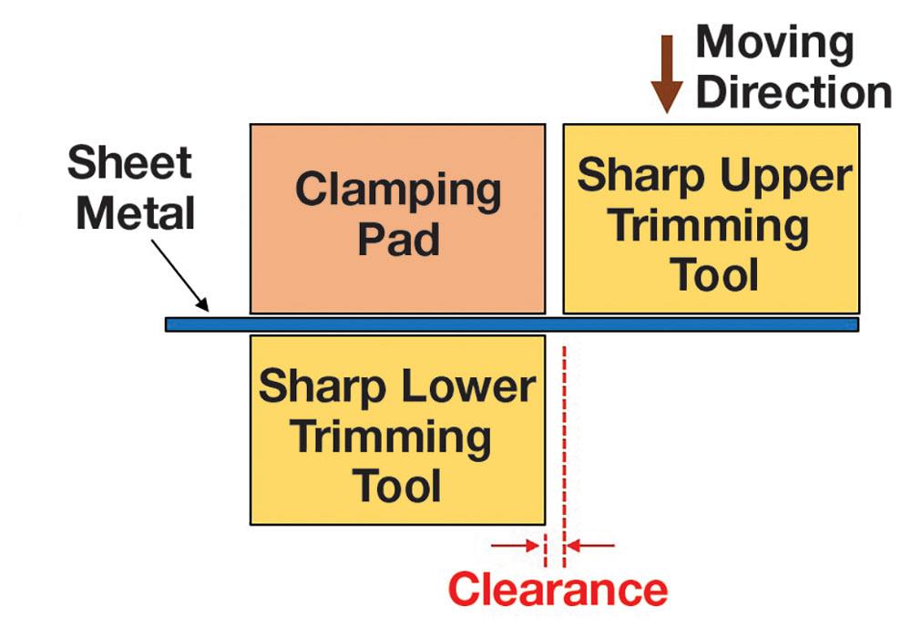
These materials usually undergo shearing operations such as blanking, piercing, and trimming (see Figure 1). In many cases, the sheared surfaces are subject to further edge stretching during later stamping and assembly operations.
Many studies have been performed on material behavior in the traditional hole expansion test, showing the results on the hole expansion ratio (HER) for sheet metal blanks with holes punched in lab-controlled conditions. Stanton et al introduced an empirical formula that attempted to predict the HER for a number of 6XXX and 5XXX aluminum alloys as a function of material thickness and ultimate tensile strength. A similar effort was performed for several steels by Comstock et al. Several empirical formulas were developed for each manufacturing method of hole fabrication, including a formula for achieving the best die clearance condition in punching.
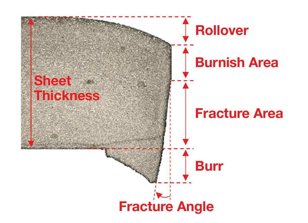
Both publications indicate that the HER for punched holes is substantially lower than for reamed holes, which means that the formability of the sheared edge will always be below the forming limit diagram. This happens because of significant plastic deformation during indentation of the cutting edges into the blank material, followed by crack propagation, which takes all available material ductility in a very narrow zone of fracture and spreads plastic deformation into the sheet for some portion of the sheet metal’s thickness. The indentation zone, which dictates the level of plastic deformation, depends on the height of the burnish zone (see Figure 2). The larger the burnish zone, the higher the shear plastic deformation occurring before fracture.
The approach described by Stanton et al and Comstock et al does not take into account shearing process parameters, which change often because of nonuniform cutting clearance, sheet metal deformation occurring before the cutting process (prestrain), and a variety of cutting angles. The effects of these parameters on 6XXX aluminum alloys have been analyzed in laboratory environments, but knowledge of real cutting parameters is required to apply these results accurately. In stamping, these parameters often are unknown because of inaccurate cutting die assembly or flexing of cutting tools during shearing, blanking, trimming, and punching.
Measuring the cutting clearance between the upper and lower shearing edges without a blank often is misleading. This geometric clearance might be subject to significant changes, as cutting forces can expand it. This typically occurs in the cam trimming mechanism. Cutting conditions also can be altered by abrasive die wear, chipped cutting edges, and adhesion of sheet metal particles on the surface of the cutting tool. All these factors create significant uncertainty in real production conditions that can vary during the life of the trim die and overall production program. Keeping cutting conditions under control and avoiding edge splitting can be challenging.
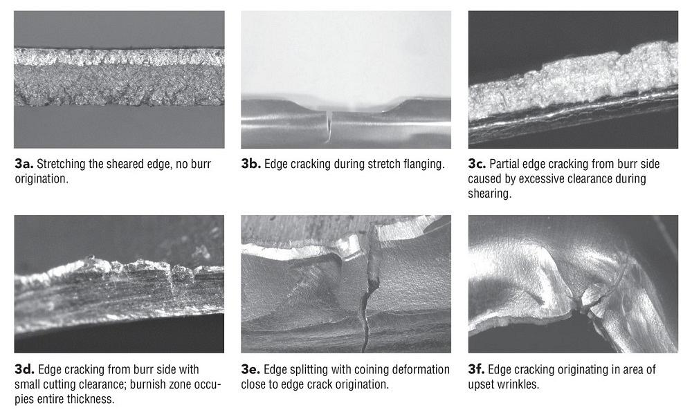
The first typical mode of edge splitting is when the edge of the material, sheared with recommended clearance providing no burr, still has insufficient formability for the current die design. In this case, multiple crosshatch cracks can occur (see Figure 3a). Since there is likely no possible improvement in the cutting process, the solution is to use more formable material or reduce edge stretching.
Another possible failure is one major crack at about 90 degrees to the sheared edge surface (see Figure 3b). This failure can be caused by excessive clearance between the cutting edges, insufficient clearance, insufficient stiffness of the die, or gradually deteriorated edges. For most materials, this type of crack initiates in the burr area, where material has the most damage. For cutting conditions leading to origination of burrs, the crack usually initiates from the upper cutting edge and then propagates to the lower edge, forming the burr around it. The final separation during cutting with excessive clearances occurs when the scrap tears off the part in the burr area, which damages the sheet material. Therefore, when further deformation is applied to the sheet metal in the form of edge stretching, edge cracking usually originates from the burr.
According to Coryell, edge fractures typically occur in the highest edge strain area in the presence of a rough trimmed edge. They often occur during drawing with blanked windows or from a stretch flange after a rough die trim. This failure mode might gradually appear on the edge of the blank in the form of cracks partially propagating through the thickness. It might occur in cases with excessive clearances (see Figure 3c), where the fracture zone occupies most of the edge surface. This failure mode also might take place in the case of insufficient clearance, where the zone of indentation (burnish zone) occupies most of the blank thickness (see Figure 3d).
The indication of excessive clearance between the cutting edges in the form of burrs might alter to a no-burr condition when burr is broken off the sheared edge, as described by Golovashchenko et al and Nasheralahkami et al. This condition is typical for UHSS and results in reduced formability with crack propagating perpendicular to the sheared surface of the blank. This failure mode can be controlled by adjusting the cutting clearance and designing the trim tools to be well supported to avoid flexing and clearance expansion.
The next failure mode, coining deformation, is visible on the left side of the crack in Figure 3e. The material was subjected to local, significant compression, likely caused by tool misalignment. This failure mode can be eliminated by proper alignment of the tool and avoiding this local indentation.
Finally, the failure mode illustrated in Figure 3f likely comes from the drawing process, when a wrinkle forms on the trim line. During trimming, the wrinkle is smashed, resulting in significant additional deformation of the material. It also may occur during secondary trimming or flanging operations. Upsetting the wrinkle creates significant local deformation of the sheared edge and likely leads to edge cracking. This failure mode may depend on the adjustment of the draw bead system in the drawing operation. Opening the flange clearance in drawing might ease the material flow into the die cavity and eliminate problems of splitting in drawing, but it also might create new wrinkles on the flange, which can be harmful. More study is needed to determine the acceptable amount of shallow wrinkling that would not bring excessive deformation for edge splitting. Wrinkling on the trim line also can be controlled by adjusting the draw beads during production. Sometimes, because of die wear, increased friction or galling in draw beads, or variability in production materials, the binder clearance is adjusted beyond the typical 10% of the sheet thickness in the draw die. Overall, this failure mode can be managed by the draw bead system to eliminate or minimize wrinkles.
References
R.J. Comstock, D.K. Scherrer, and R.D. Adamczyk, “Hole Expansion in a Variety of Sheet Steels,” Journal of Materials Engineering and Performance, Vol. 15 (2006), pp.675-683.
J.J. Coryell, “Edge Fracture in Mixed Microstructure Steel,” presented at Great Designs in Steel 2016, sponsored by The American Iron and Steel Institute.
S. Golovashchenko and R. Sohmshetty, “Evolution of Die Wear and Sheared Edge Parameters in Trimming of DP980 Steel,” presented at Great Designs in Steel 2017, sponsored by The American Iron and Steel Institute.
S. Nasheralahkami, W. Zhou, and S. Golovashchenko, “Study of Sheared Edge Formability of Ultra-High Strength DP980 Sheet Metal Blanks,” Journal of Manufacturing Science & Engineering, Vol. 141, No. 9 (2019).
M. Stanton, R. Bhattacharya, I. Dargue, R. Aylmore, and G. Williams, “Hole Expansion of Aluminum Alloys for the Automotive Industry,” AIP Conference Proceedings, Vol. 1353 (2011), pp. 1488-1493.

Professor and Director
Oakland University Center of Advanced Manufacturing and Materials (CAMM)


The Fabricator is North America's leading magazine for the metal forming and fabricating industry. The magazine delivers the news, technical articles, and case histories that enable fabricators to do their jobs more efficiently. The Fabricator has served the industry since 1970.
start your free subscription
Easily access valuable industry resources now with full access to the digital edition of The Fabricator.

Easily access valuable industry resources now with full access to the digital edition of The Welder.

Easily access valuable industry resources now with full access to the digital edition of The Tube and Pipe Journal.

Easily access valuable industry resources now with full access to the digital edition of The Fabricator en Español.
Seth Feldman of Iowa-based Wertzbaugher Services joins The Fabricator Podcast to offer his take as a Gen Zer...


