


Professor and Director
Getty Images
In the automotive industry, the use of advanced and ultrahigh-strength steels (AHSS/UHSS) continues to expand, as these materials can help reduce vehicle weight while adding strength and improving fuel economy and crashworthiness.
The process of stamping parts from sheet metal frequently includes shearing operations such as blanking, piercing, and trimming. In all these processes, shearing edges of the die indent into the sheet material until fracture propagates between the upper and lower shearing edges (see Figure 1).
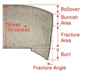
A sheared metal edge typically has four zones (see Figure 2) that are found on the edges of both the cut-off piece and the clamped piece, but in alternate orientations:
Many factors can affect the configuration of the sheared edge such as the cutting clearance, cutting angle, cutting blade sharpness, cutting speed, lubrication, sheet material parameters, tooling condition, tool wear, and strain rate.
Let’s take a closer look at a few of these factors.
The clearance is the horizontal distance between the upper and the lower shearing edges in trimming (see Figure 1) and the radial distances between the round punch and die in hole punching. It is normally expressed as a percentage of the sheet metal thickness. For mild steel, it varies between 5% and 12% of the sheet thickness.
Trimming clearance is a major factor in determining the shape and quality of the sheared edge. Optimizing the clearance may require some experimentation to minimize an uneven fractured edge condition.
Increasing clearance decreases pressure on the cutting tool, which helps increase tool life. A limiting factor is the quality of the sheared edge and allowable burr height. Decreasing clearance helps improve shear edge quality, but it increases deformation of the sheet material in the shearing zone. It also increases work hardening and results in larger cutting forces and higher loads on the cutting edges of the die.
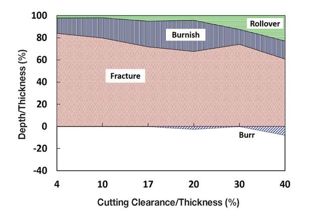
Figure 3 shows the experimental plot representing the effect of cutting clearance on the depth of rollover, burnish, and fracture zones and the burr height for 1.45-mm-thick UHSS DP980 sheet material.
The part edge quality also depends on the material being sheared. Materials with high ductility, low yield strength, and homogeneity will have a better sheared edge quality, dimensional tolerances, and longer tool life.
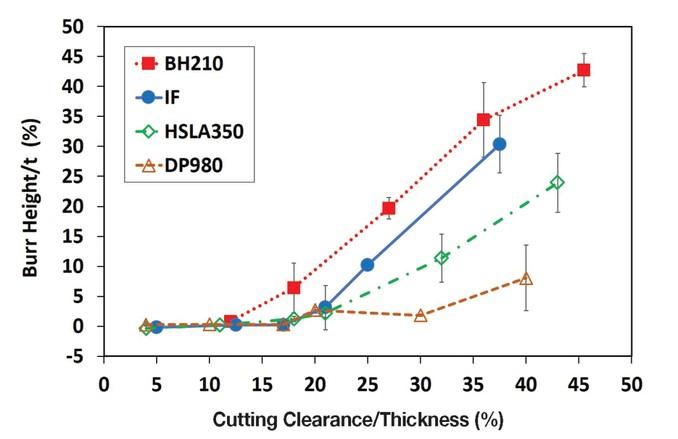
Burr heights with respect to the cutting clearance for different sheets, including interstitial-free (IF) mild steel, bake-hardenable steel (BH210), high-strength steel (HSLA350), and UHSS DP980, are plotted in Figure 4. On all these sheet materials, burr height grows with increased clearance and ductility.
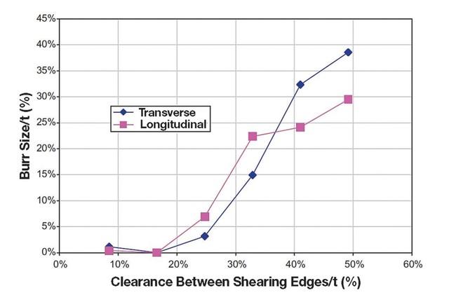
Material anisotropy also can affect the part edge quality; for anisotropic materials, different trim line orientations relative to the rolling direction give different sheared edge features.
Figure 5 shows burr heights versus trimming clearance for DP500 steel and different trim line orientations relative to rolling direction, including transverse and longitudinal directions.
Tool wear is an important factor directly affecting the sheared edge quality. Tool wear is the gradual failure of shearing tools from regular, repeatable use. As trimming tool wear progresses, the edge profile and dimensional accuracy of the trimmed part deteriorate significantly.
Trimming of AHSS/UHSS creates high contact pressure and friction force between the tools and sheet blank, so these conditions lead to galling, chipping, and abrasive and adhesive wear in the trimming tools. Furthermore, the presence of the hard martensitic phase in the microstructure of AHSS/UHSS can intensify the tool wear.
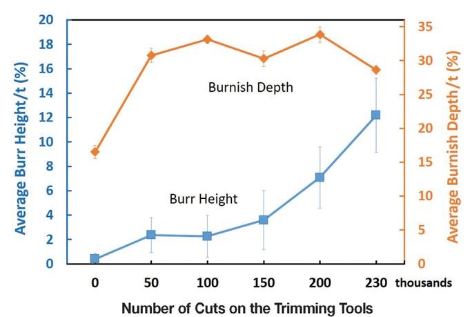
Figure 6 illustrates the effect of cutting cycles as an indication of tool wear on the average burr height and burnish depth of DP980 sheet material. As shown in this figure, both burr height and burnish depth increase as tool wear increases. With tool wear progressing at the edge, it gradually gets duller. A tool with an edge that’s dulled by wear and microchipping can allow material flow instead of promoting large shearing deformation and fracture of the blank. Therefore, wear on the die’s cutting edge increases burr height and burnish zone.
The burnish zone and rollover area reflect the penetration depth of the cutting tool to reach the critical damage at which fracture initiates. In the case of DP980, with increased cutting cycles and progressing tool wear, the indentation of the upper tool into the blank to reach fracture increases, so the burnish area increases.
Burr height generally is an important criterion to evaluate part quality in stamping operations. Burr height indicates when the tool should be reground to obtain the sharp die-and-punch radius. Therefore, trimming die wear can be monitored offline by observing the shape of the trimmed edges on the part. Measuring the burnish area and burr height can indicate when die maintenance is required.
References
S. Nasheralahkami, W. Zhou, and S. Golovashchenko, “Study of Sheared Edge Formability of Ultra High Strength DP980 Sheet Metal Blanks,” ASME Journal of Manufacturing Science & Engineering, Vol. 141, No. 9 (2019).
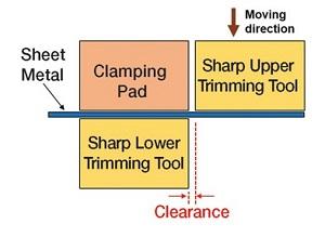
FIGURE 1. In the trimming process, shearing edges of the die indent into the sheet material until fracture propagates between the upper and lower shearing edges.
A. M. Ilinich, S.F. Golovashchenko, and L.M. Smith, “Material Anisotropy and Trimming Method Effects on Total Elongation in DP500 Sheet Steel,” Journal of Materials Processing Technology, Vol. 211, No. 3 (2011), pp. 441-449.
T. Altan and A.E. Tekkaya, eds., Sheet Metal Forming; Processes and Applications (Materials Park, Ohio: ASM International, 2012).

Professor and Director
Oakland University Center of Advanced Manufacturing and Materials (CAMM)

PhD Candidate
Oakland University Center of Advanced Manufacturing and Materials (CAMM)


The Fabricator is North America's leading magazine for the metal forming and fabricating industry. The magazine delivers the news, technical articles, and case histories that enable fabricators to do their jobs more efficiently. The Fabricator has served the industry since 1970.
start your free subscription
Easily access valuable industry resources now with full access to the digital edition of The Fabricator.

Easily access valuable industry resources now with full access to the digital edition of The Welder.

Easily access valuable industry resources now with full access to the digital edition of The Tube and Pipe Journal.

Easily access valuable industry resources now with full access to the digital edition of The Fabricator en Español.
Seth Feldman of Iowa-based Wertzbaugher Services joins The Fabricator Podcast to offer his take as a Gen Zer...


