


Business Development Manager, Automotive Division,
To prevent wear and tear on the hydraulic press, it is best to make sure the press has been engineered to mitigate the water hammer effects inherent in a fluid power system.
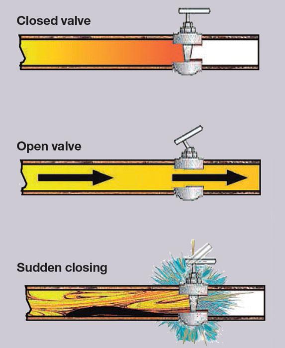
Since time immemorial, people have known the destructive effects of a quick, sharp hit (think medieval battering rams). A sudden impact produces forces greater than pressure alone. The water hammer effect results when a moving element collides with a stationary one. These elements may be mechanical or hydraulic (see Figure 1).
Following the discovery of underground hydraulic chambers in Giza, some theorize that the Egyptians built chambers that generated the water hammer effect to help them construct the great pyramids (see Figure 2).
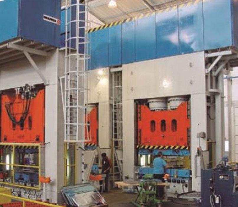
Today hydraulic presses work by making oil flow at pressure to one or several cylinders that, when filled, drive pistons that move the slide supporting the die (see Figure 3). Evidently, modern presses need to have many different ways of working and move at high speed. As a result, oil flow is never calm and stable. The complexity of the tubing, its pathway, pump and valve operations, and accelerating and braking activate this flow frequently and then interrupt it.
By definition, the “water hammer effect,” also called the Zhukovsky pulse, first studied by Russian engineer Nikolai Zhukovsky, is a pressure wave that is created when a fluid is forced to change speed suddenly. This surge, or wave, moves at the speed of sound through a pipeline system. The water hammer effect damages machines because it causes vibrations, sudden sharp pressure increases, and high stress on mechanisms and piping.
In fact, the word hammer really is a suitable description. The tubing, vanes, and valve slides receive an impact that is reminiscent of an ancient trireme ramming its enemy or the tree trunks used by our medieval ancestors to knock down fortress gates. This natural effect occurs in all fluid pipeline systems.
Therefore, preventing the water hammer effect is an important task for hydraulic press designers. Engineering R&D has concentrated on designing hydraulic circuits in presses to minimize it.
The water hammer effect is directly linked to the compressibility of fluids. Although oil does not have a high level of compressibility, it does exist and is high enough to cause this phenomenon. It is particularly significant when the high pressure found in a hydraulic press is taken into account. It is a complex phenomenon that is not fully understood, but that has been modeled over time with sufficient accuracy.
When a valve is closed rapidly, or there is an obstruction in the system, the fluid molecules that are in direct contact with the mechanism are stopped (see Figure 4). However, trillions of molecules continue moving forward behind them. This causes a significant increase in pressure, generating a wave that travels along the tube at a speed dependent on the speed of sound and the shape of the pipeline system.
This excess pressure has two effects. First, as described, the fluid is compressed, reducing its volume. Second, the tubing, pumps, and valves expand slightly. A moment later, when the pressure wave has traveled along the entire pipeline system and all the oil has stopped, the excess pressure falls, the liquid expands once again, and the tubing compresses to its normal diameter. These effects then cause a second pressure wave that travels in the opposite direction. Therefore, the pressure wave moves in a forward and backward motion. The oil is then driven in the other direction, but as the end is closed off and no more fluid follows behind, a heavy depression is caused that contracts the tubing.
This action can destroy the tubing or convert the suddenly decompressed oil into a gaseous state, creating bubbles at the very moment the tubing is contracting, thereby creating more surges. Vibrations are also produced and the sound level increases.
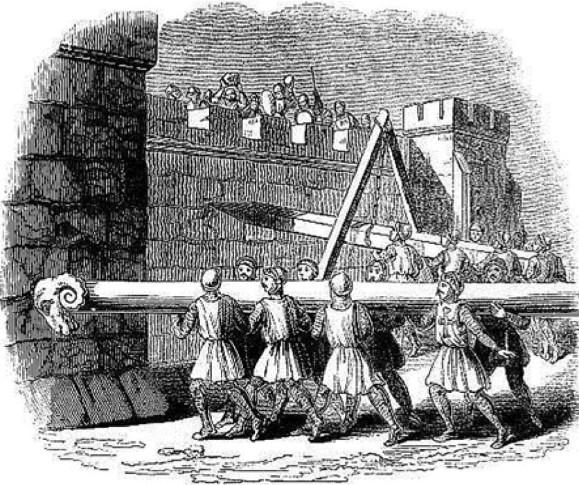
Figure 1
Medieval battering rams were one of the most demonstrative uses of the hammer effect.
The excess pressure produced before the oil is suddenly stopped can be roughly calculated using the Zhukovsky equation:
Where ρ is the fluid density and C is the speed at which the pressure wave travels through the fluid and tubing. The equation is based on the fundamental physical principle of the momentum conservation that relates a pressure increase to a speed increase. Dividing both terms in the equation by the (ρ.g) factor produces a static pressure value of:
Where C is the wave speed in relation to the fluid speed, Vo is the average fluid speed in steady conditions, and g is acceleration caused by gravity.
The wave speed depends on both the fluid and the pipeline system, calculated as follows:
Where E is the modulus of elasticity of the tube material, D is the tube’s inner diameter, and e is its wall thickness. K is the modulus of elasticity of the fluid, and ρ is the fluid density. For rigid tubing, the square root of the numerator is the same as the speed at which sound is propagated in the fluid, so the following can be stated:
This shows that, even in a simple pipeline system, the tube’s diameter and thickness have a significant effect on the speed at which the shock pulse moves and, therefore, excess pressure is produced (see Figure 5). The greater the tube thickness, the slower the speed and excess pressure. This is also true for the diameter. In addition, the lower the elasticity limit, the lower the excess pressure. This means that, for example, an aluminum tube is better than a steel tube for this purpose.
The wave propagation time from the closed valve to the mouth of the tube will be:
where L is the length of the tube.
It also is possible to determine whether there is a risk of the water hammer effect depending on how much time it takes the valve to close. Where this time to close = Tc:
If Tc ≤ Tp, closing is essentially instantaneous because the closing time is less that the time the pressure wave takes to travel back and forth. Water hammer will be produced.
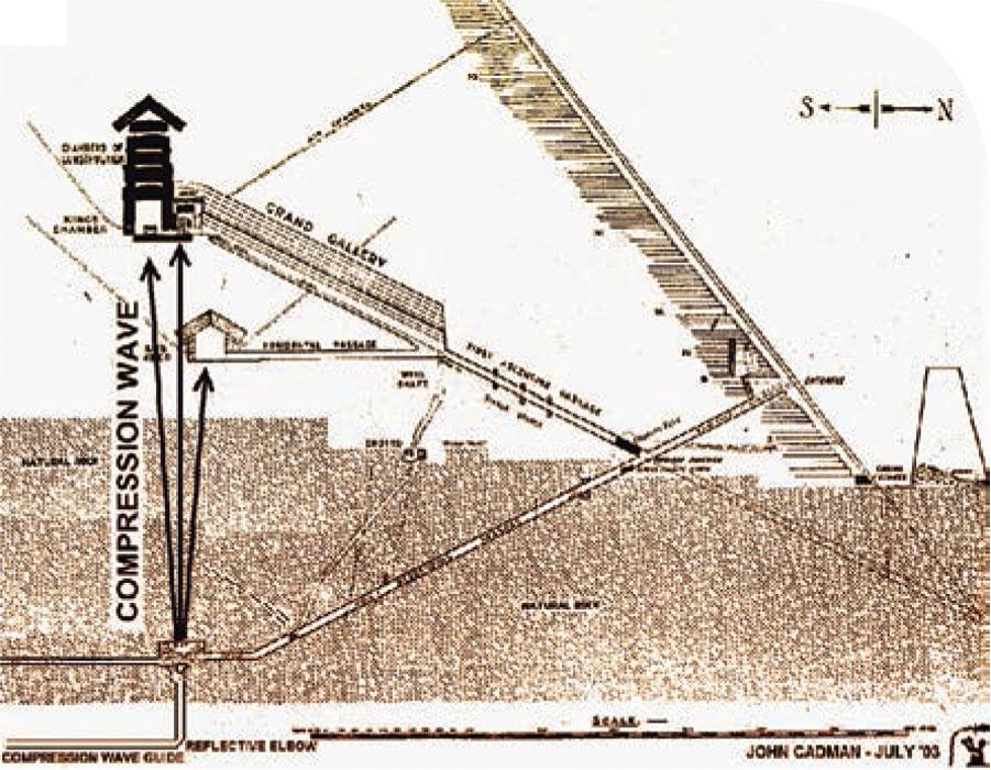
Figure 2
Some theorize that a hydraulic pulse mechanism was used to create a hammer effect used to move stone blocks in the construction of the pyramids. Image courtesy of John Cadman, “The Great Pyramid’s Subterranean Chamber Hydraulic Pulse Generator and Water Pump.”
If Tc > Tp, water hammer will not be produced because the pressure wave will return to the valve before it has fully closed and some of this excess pressure will be able to pass through it.
These calculations can be used to determine the suitable length, thickness, and diameter of a tube.
Calculations also can be made to design the tube properly to withstand the stress a pressure wave will cause to a tube. The pressure the wall of a conducting tube can withstand, according to the fluid pressure, is:
Where Hm is the manometric height of the pump pressure the tube must withstand (in Pa), di is the inner diameter, in millimeters, of the tube, and e is its thickness. When excess pressure is produced, Hm can be replaced by ∆H to determine the stress the tube will have to withstand.
Although the basic physics is straightforward, the actual calculation becomes infinitely more complicated because, in practice, tubes are neither straight nor uniform in shape. Pipeline systems are intricate, with valves between tubes, vibrating pumps, simultaneous actions, vibrations generated by the press caused by mechanical movement, different types of tube (rigid or flexible), the short duration of these transient phenomena, and so forth.
Although software packages have been specially designed to simulate water hammer under specific conditions and various differential equation models have been developed that simulate unstable conditions, it remains difficult to calculate a complex pipeline system accurately.
This is the point at which experience and the manufacturer’s guidelines come into play to minimize any unwanted effects.
The hydraulic press has a useful life of several decades, but conditions are unpredictable, so it is important that it is designed to prevent or minimize the water hammer effect and its consequences. Stamping manufacturers are advised to check that some or all of the following measures have been taken in the design and build of a press they are considering for purchase or are operating to extend press life.
1. Hoses or flexible tubing can be used when regulations permit. Flexible tubing absorbs the pulse that the water hammer creates because the wave propagation also depends on the conducting material. Rubber and plastic materials reduce the effect.
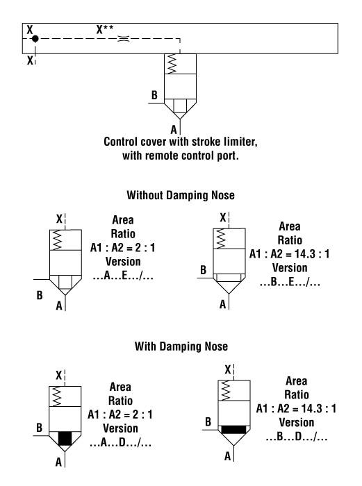
2. Mechanical regulators soften the opening and closing of the logic elements, preventing the water hammer effect. It is important to compare the closing time with the time the sound wave takes to travel back and forth. There are two options: limiting the flow and damping the part (see Figure 6).
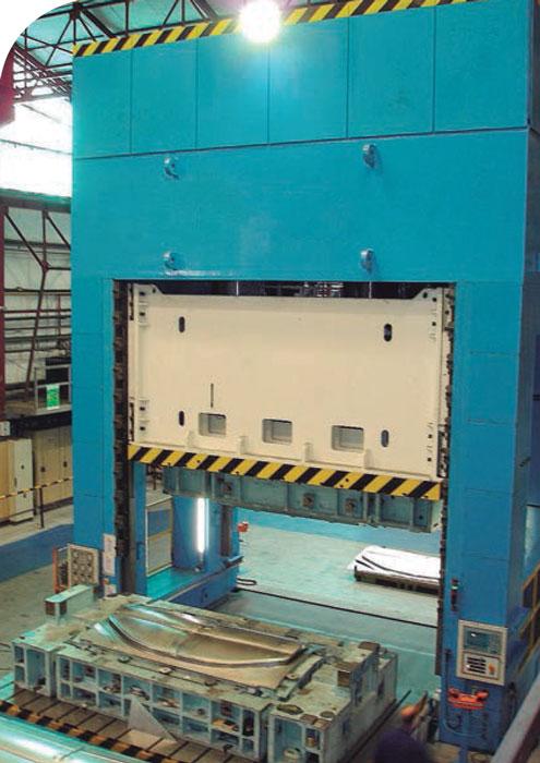
Figure 3
Hydraulic presses work by making oil flow at pressure to one or several cylinders that, when filled, drive pistons that move the slide supporting the die.
3. Gradual slide braking can reduce the effect. When the slide moves from the approach cycle at a high speed to the work cycle, there is a heavy pulse. A proportional valve is used to control this braking so that the slide brakes gently, regardless of the size of the die it is supporting.
4. Another technique that reduces the effect is gradual decompression. Oil flows heavily through the hydraulic circuit at the moment of decompression. Although a rapid decompression shortens cycle time, it also increases the flow through the machine and magnifies the water hammer effect. Therefore, using a proportional valve can achieve rapid yet gentle decompression that ramps down the pressure.
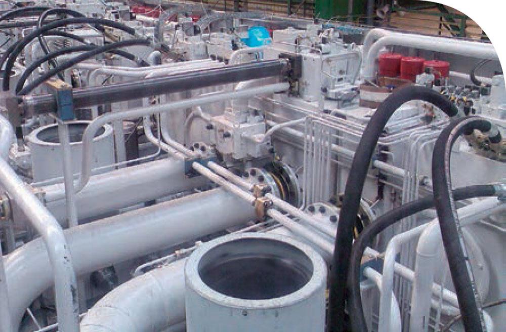
5. Group manifolds with integrated injectors can help as well. The injectors are used to ensure the parts work smoothly. When a heavy flow passes through an injector, it limits the flow and regulates the movement of the part that it controls. This helps to reduce pressure peaks and hydraulic pulses. These pulses also can damage parts such as transducers and pressure switches.
6. Correct installation of clamps and tube supports is extremely important for maintaining their useful life. In the event that pulses occur, leakage or cracks at joints will result if the tube has not been well-supported.
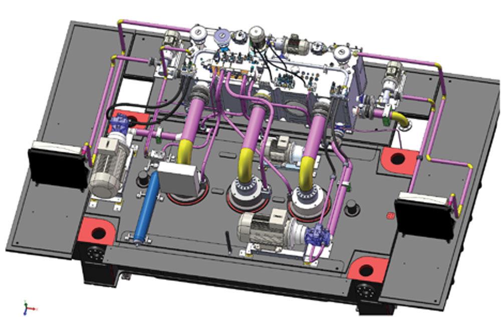
7. To mitigate problems that the water hammer effect can cause, hydraulic press installations should be designed first using 3-D modeling (see Figure 7). The 3-D design can be used to study and optimize the tube route, analyze sections, and so forth, avoiding unnecessary pulses that damage the tube. To install clamps correctly and maintain the tubing and piping properly, it is vital that unnecessary curves and complex routes have been avoided.
8. Simulating the design first using 3-D modeling ensures that all possible solutions to the water hammer effect have been implemented to achieve the best hydraulic installation. The optimal design minimizes the number of elbows in the piping, previews the best location for the clamps, and allows easy access for maintenance.
Finally, during setup, it is important that the press system has been checked with a high-performance SCADA so that the hydraulic equipment is perfectly fitted. This ensures that the press leaves the factory without any pressure peaks that could cause problems in the future.


The Fabricator is North America's leading magazine for the metal forming and fabricating industry. The magazine delivers the news, technical articles, and case histories that enable fabricators to do their jobs more efficiently. The Fabricator has served the industry since 1970.
start your free subscription
Easily access valuable industry resources now with full access to the digital edition of The Fabricator.

Easily access valuable industry resources now with full access to the digital edition of The Welder.

Easily access valuable industry resources now with full access to the digital edition of The Tube and Pipe Journal.

Easily access valuable industry resources now with full access to the digital edition of The Fabricator en Español.
Seth Feldman of Iowa-based Wertzbaugher Services joins The Fabricator Podcast to offer his take as a Gen Zer...


