


R&D Update: Sequence design for progressive dies, Part I
Part I: Using FE-based methodology

Progressive-die design relies heavily on past experience and several prototyping runs. The most challenging issue in designing a process sequence is how to determine the minimum number of required forming stages and corresponding tooling geometry to satisfy specification for thickness, residual stresses, and surface finish.
Progressive-die Sequence Design
Every process sequence design must include the number of forming stages, tool geometry for each stage (punch and die diameter, punch corner, and die corner radii), draw depth for each forming stage, and blank holder force (if needed) at each stage.
Process sequence design for a new part generally is based on experience-knowledge gained from producing similar parts and necessary prototyping runs. This experience-based methodology requires extensive resources and increases the design’s lead-time. Finite element analysis (FEA), coupled with knowledge-based design, can strategically reduce lead-times and enhance the robustness of the progressive-die sequence. A robust process accounts for variability during production, such as:
- Variations in incoming stock material properties.
- Variations in process conditions (forming speed, force, and so forth) and interface characteristics (lubrication and frictional forces) thickness distributions and strain hardening were predicted for each stage and carried over to the successive stage to account for work hardening.
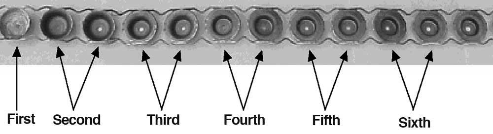
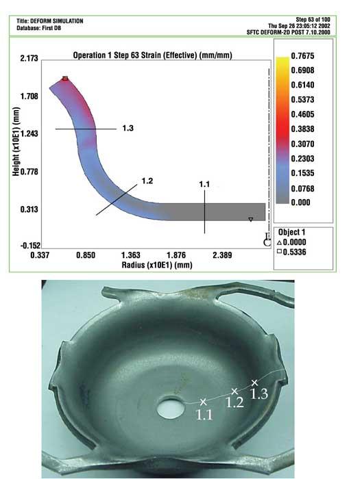
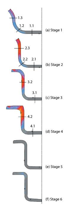
Figure 3 shows the part’s strain (thickness) distribution as predicted by FEA after the first stage. At each stage, FEA accurately predicted strain distribution, part geometry, and punch forces. Figure 4 shows the final part geometry predicted by FEA for all six forming stages.
Based on FEA of the existing automotive part, general design guidelines were created that could assist process sequence design for a new part. Some guidelines were:
- To maintain maximum wall thinning below a threshold value of 13 percent, higher draw ratios were required in the initial forming stages. This finding corroborates guidelines already followed by experienced die designers.
- Punch corner radii and die corner radii were critical parameters in the initial forming stages. The die corner radius was selected based on initial sheet thickness (about four times the incoming sheet thickness). The punch corner radius was selected based on the die corner radius (approximately equal to or less than the corresponding die corner radius).
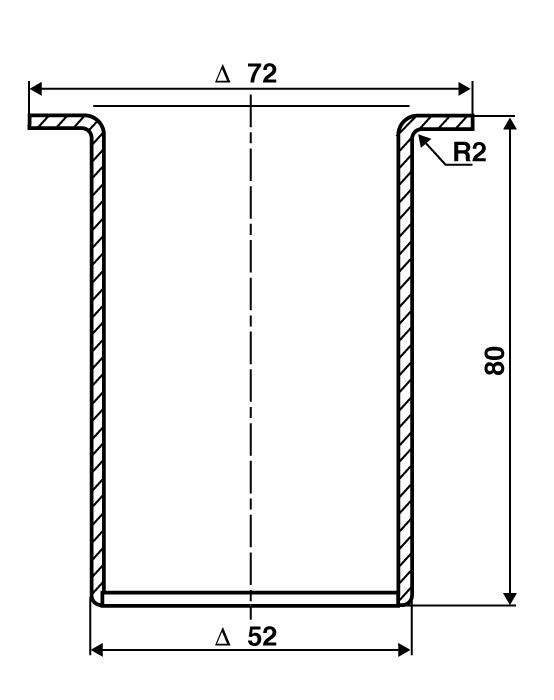
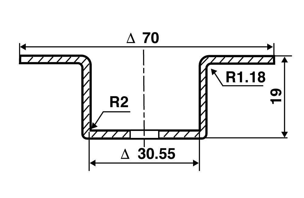
The depth of the new part (Figure 2a) would be significantly greater than the depth of the existing automotive part (Figure 2b), so more than six forming stages would be needed for the new part.
These design rules garnered from the FEM study will be used to develop the process sequence for the new automotive part, which will be discussed in Part II.
About the Publication

subscribe now

The Fabricator is North America's leading magazine for the metal forming and fabricating industry. The magazine delivers the news, technical articles, and case histories that enable fabricators to do their jobs more efficiently. The Fabricator has served the industry since 1970.
start your free subscription- Stay connected from anywhere

Easily access valuable industry resources now with full access to the digital edition of The Fabricator.

Easily access valuable industry resources now with full access to the digital edition of The Welder.

Easily access valuable industry resources now with full access to the digital edition of The Tube and Pipe Journal.

Easily access valuable industry resources now with full access to the digital edition of The Fabricator en Español.
- Podcasting

Seth Feldman of Iowa-based Wertzbaugher Services joins The Fabricator Podcast to offer his take as a Gen Zer...


