


R&D Update: Sequence design for progressive dies, Part II
FE-based design methodology
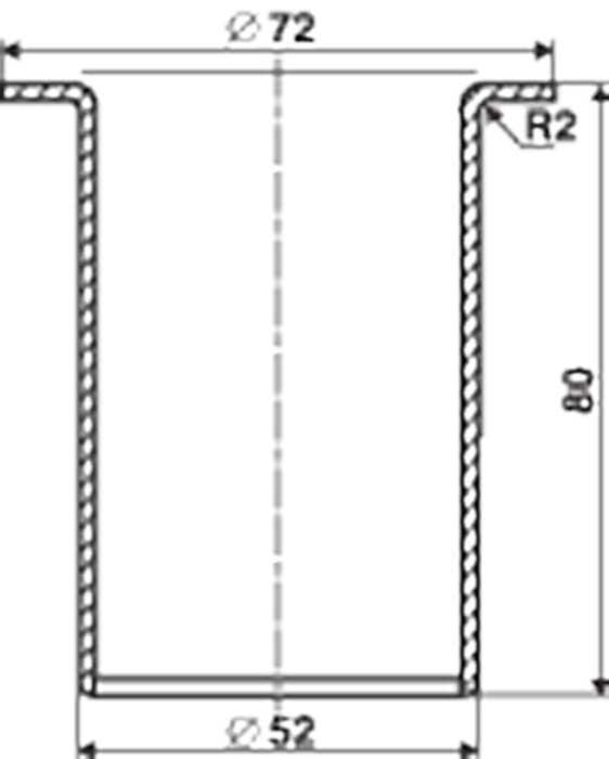
- In the initial forming stages, higher draw ratios maximized wall thinning below a threshold value of 13 percent for the existing automotive part (see Figure 1b ).
- Punch corner radii and die corner radii also were critical parameters in the initial forming stages. The die corner radius (approximately four times the incoming sheet thickness) was selected based on the sheet thickness. The punch corner radius was chose based on the die corner radius (approximately equal to or less than the corresponding die corner radius).
FEA of the New Part
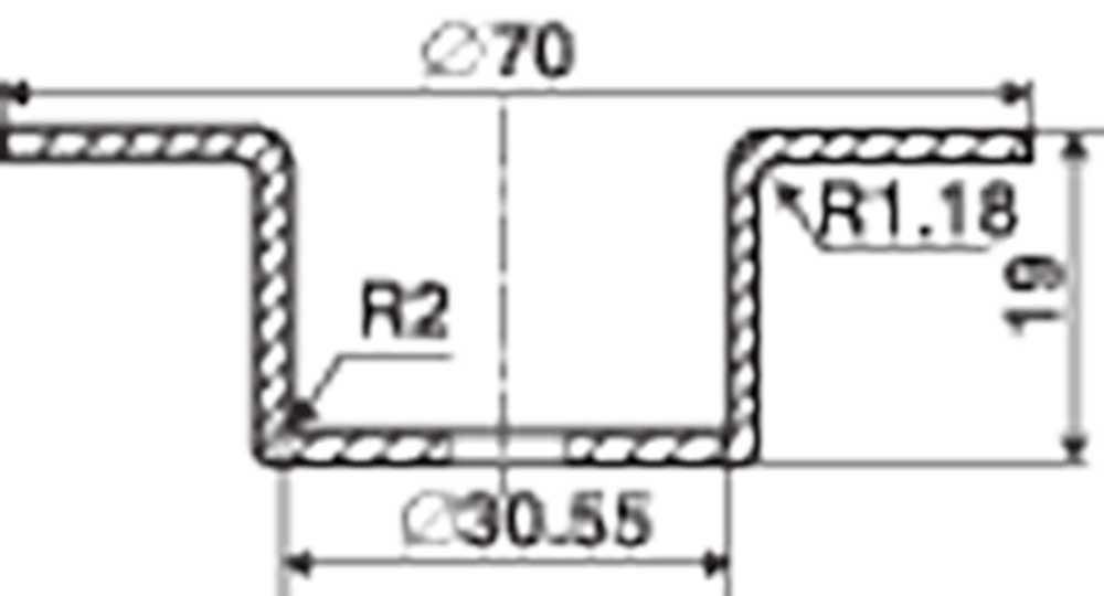
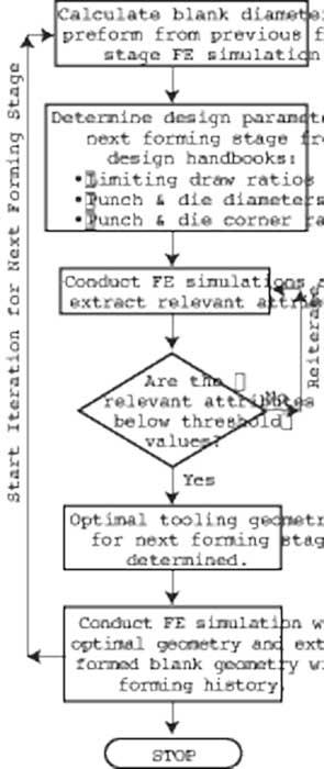
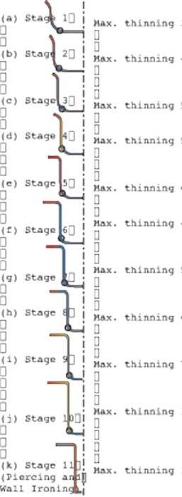
These design guidelines and others from die design handbooks helped to develop the progressive-die sequence for the new automotive part (see Figure 1). Figure 2 illustrates the process in sequence to determine the optimal design parameters for each forming stage using commercial FE code DEFROMTM -2D software (www.deform.com).
Critical parameters calculated during the die sequence design phrase were:
- Initial blank dimensions . The approximate blank dimensions from the final part shape were calculated using volume constancy.
- Blank holder force. At each forming stage, blank holder force was estimated as the minimum blank holder force required to eliminate the formation of flanges wrinkles.
- Optimal punch and die dimensions and draw depth. Punch diameter and drawing depth have the most influence on wall thinning. FE simulations varying the limiting draw ratios and the punch diameter were conducted. Combinations of punch diameters and draw depths were selected by minimizing part thinning below an established threshold value at each forming stage.
Once the optimal punch diameter was found, FE simulations using different punch corner and die corner radii sets were conducted. Also in these simulations, the ratio of punch corner radius to die corner radius was kept to less than one based on guidelines obtained from die design investigation of the existing automotive part.
The most important output from FEM simulations was the location of the part’s maximum thinning. Design engineers used this information to select punch diameters for subsequent production stages. In subsequent forming stages, determining the punch diameter prevented the punch from striking the part at its maximum thinning location. Successive strikes in the area of maximum thinning would result in significant wall thinning. Figure 3 shows the geometry ad the effective strain (thickness) distribution predicted by the FEA for forming the new automotive part.
Comparing FEM, Experience-based Methods
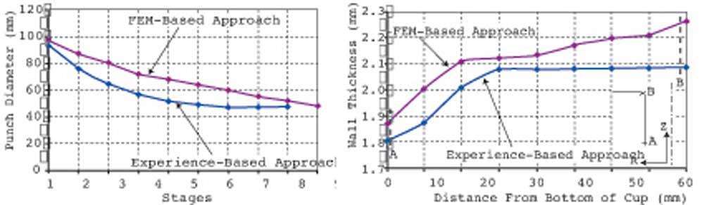
Figure 4 compares punch diameters and thickness distributions as predicted by the FE-based method and experience-based approach. The FE-based method predicted 10 forming stages, while the experience-based approach predicted nine forming stages.
The change in punch diameters in subsequent forming stages predicted by the FE-based method is gradual, while larger punch diameter reductions were observed in the experience-based approach. Thickness distributions obtained from these two designs showed that gradual change in punch diameter resulted in a more uniform wall thickness distribution in the final stages. The comparison of punch corner and die corner radii change for various stages showed a similar trend for both the FEM-assisted and experience-based approaches.
What We Learned
This study demonstrated that integrating computer-aided engineering (CAE) with the experience of tool designers who understand the process can reduce sequence development time. CAE also can help speed up the process of designing geometrically complex part that normally require a lot of trial and error.
With process simulation, critical attributes such as strain (thickness) distribution, stress distribution, material flow, and forming defects can be estimated easily. This knowledge enhances the design capability of an experienced process designer and reduces the number of die tryout.
The use of FEM further refines die design so product attributes such a wall thickness tolerances can be improved. To make FEM a practical tool for designing progressive and transfer dies in the stamping industry, close cooperation between experienced die designers and FEM engineers is key.
About the Publication

subscribe now

The Fabricator is North America's leading magazine for the metal forming and fabricating industry. The magazine delivers the news, technical articles, and case histories that enable fabricators to do their jobs more efficiently. The Fabricator has served the industry since 1970.
start your free subscription- Stay connected from anywhere

Easily access valuable industry resources now with full access to the digital edition of The Fabricator.

Easily access valuable industry resources now with full access to the digital edition of The Welder.

Easily access valuable industry resources now with full access to the digital edition of The Tube and Pipe Journal.

Easily access valuable industry resources now with full access to the digital edition of The Fabricator en Español.
- Podcasting

Seth Feldman of Iowa-based Wertzbaugher Services joins The Fabricator Podcast to offer his take as a Gen Zer...


