


R&D Update: Springback in stamping, Part I
Springback causes geometric changes in the final shape of the part, so it is very important, particularly if tight tolerances have to be held. With the increased use of high-strength materials, predicting and correcting springback become increasingly critical. For example, high-strength, low alloy steel (HSLA) and various aluminum alloys often are considered direct replacements for automotive body panels, but spingback is one of the principal difficulties preventing their widespread adoption.
Factors Affecting Springback
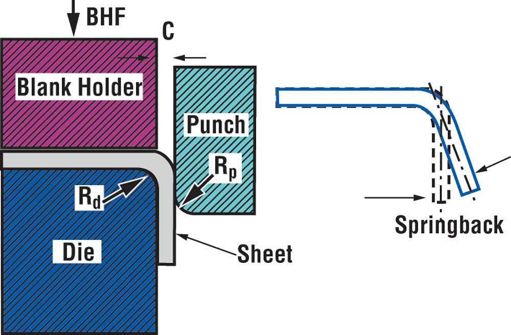
To reduce spingback in stamping, it is necessary to understand the important factors that cause it. The simple, commonly used testing methods used to analyze these factors include U-bending and flanging (see Figure 1 ). The U-bending method illustrates the springback behavior of a sheet material undergoing drawing or bending-unbending deformation, while the flanging method shows the springback behavior of material in a simple bending operation.
Springback in stamping is influenced mainly by the sheet material properties and process parameters.
Sheet Material Properties. The sheet material by the sheet material properties affecting springback are:
- Elastic modulus— Also known as Young’s modulus, this property states the stress-strain relationship of a material undergoing elastic deformation. It is measure of the elastic recovery of a deformed part and, therefore, directly affects springback. As Young’s modulus decreases, spingback increases.
- Strain hardening — As the material deforms, its overall strength increases. This phenomenon is called strain hardening or work hardening and usually is represented by a strain hardening exponent. Springback increases with a decrease in the strain hardening exponent.
- Anistropy— Sheet metal for stamping is produced by rolling, which causes different amounts and types of grain deformation in the rolling and transverse directions. As a result, the sheet does not deform uniformly in all directions. This material characteristics, that is, the difference in deformation properties in the rolling and transverse directions, is called anisotropy of the material. Springback in sheet material increases with an increase in anisotropy.
- Die radius (Rd ) and punch radius (Rp )— Spingback decreases with increasing die radius and decreasing punch radius.
- Die gap (c) — the amount of springback can change significantly with a small variation in the die gap. In general, springback decreases as the die gap decreases.
- Friction condition- In stamping, friction predominately exists at the die/sheet interface and the punch/sheet interface. Springback decreases as friction increases at these interfaces.
- Blank holder force (BHF)— The blank holder or binder plays a key role in sheet metal forming. Springback decreases with increasing BHF because it causes stretching in the formed part. Conventionally, BHF is applied uniformly on the blank holder and help constant during the forming process. Also, the magnitude of BHF for a given part often is determined by past experience and trial and error.
Process Parameters. These parameters are shown for simple U-bending and flanging in Figure 1:
Recent investigations have shown that a better-designed BHF profile, which varies in location and in time, can improve stamping quality and reduce springback.
Finite Element Method (FEM) Simulations in Stamping
Springback as already described applies to simple stamping process such as U-bending and flanging. Most components used in the industry, though, are much more complex, and the given guidelines may not hold true. In such cases, FEM simulations, using commercially available software, are helpful in predicting springback.
FEM provides a numerical trial-and-error procedure to simulate a stamping operation and predict springback. This reduces lead-time and is an economical process design method.
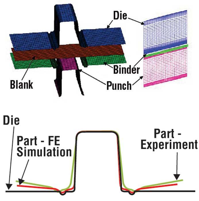
Figure 2 shows an FEM analysis of a U-channel part forming conducted at The Ohio State University’s Engineering Resource Center for Net Shape Manufacturing (ERC/NSM). The analysis was done to study the influence of variable BHF on the stress and strain histories that would reduce springback.
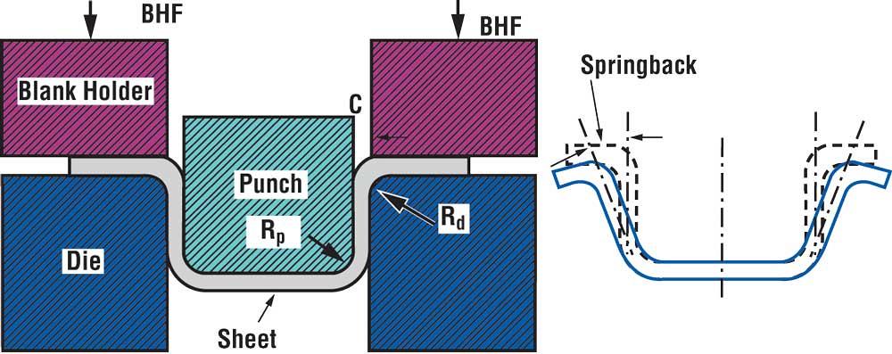
Figure 1a
U-bending is a testing method that shows springback behavior of a sheet metal undergoing drawing or bending-unbending.
Today product and process engineers rely heavily on results from FEM simulation to determine the manufacturability of a stamping component, although the prediction of springback still is not very reliable. Springback prediction is found to be quite accurate for simple geometries, but for couplex components, it fails to give results that compare well with experimental results.
There are several reasons for this failure. One appears to be the choice of the material hardening law. The material hardening law is an equation that shows the relationship between the stress and strain induced in the material as it hardens with deformation. The material law should model accurately the deformation behavior of the material being used. Also, from an industrial standpoint, the material hardening law should use a small number of parameters use a small number of parameters that can be easily determined with simple test.
Another reason is the elastic modulus of the material, which varies with plastic deformation. Work hardening of material during forming cases and appreciable decrease in the elastic modulus and thus affects springback calculation. Research is being conducted to take into consideration the variables that affect the deformation of sheet material (material deformation, stress-strain curve, and elastic modulus). The goal is to improve the accuracy of FEM simulation predictions of springback.
About the Publication

subscribe now

The Fabricator is North America's leading magazine for the metal forming and fabricating industry. The magazine delivers the news, technical articles, and case histories that enable fabricators to do their jobs more efficiently. The Fabricator has served the industry since 1970.
start your free subscription- Stay connected from anywhere

Easily access valuable industry resources now with full access to the digital edition of The Fabricator.

Easily access valuable industry resources now with full access to the digital edition of The Welder.

Easily access valuable industry resources now with full access to the digital edition of The Tube and Pipe Journal.

Easily access valuable industry resources now with full access to the digital edition of The Fabricator en Español.
- Podcasting

Seth Feldman of Iowa-based Wertzbaugher Services joins The Fabricator Podcast to offer his take as a Gen Zer...


