


Servo Press Scientist
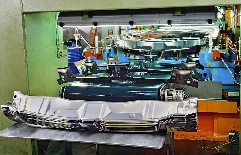
Researchers at the Center for Precision Forming share their methodology for predicting off-center loading in a transfer die set. Getty Images
Editor’s Note: This is Part II of a two-part series. Part I discussed how to predict off-center loading when forming with a single tool.
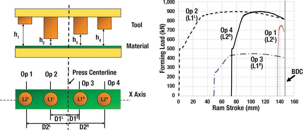
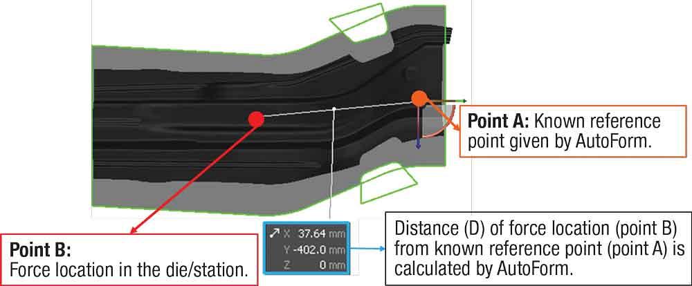
In a transfer die forming operation, a blank/initial part is transferred to several individual dies/stations to form the final part. As illustrated in Figure 1, differences between the forming and cutting forces and the distances of the individual stations from the press center can generate an off-center load, which leads to an imbalance on the press (trying to tilt the press bolster). Because the press is large, the magnitude of this imbalance produced by each station also is large. Therefore, off-center loading is a more critical issue in a transfer die forming operation than in a single die forming operation.
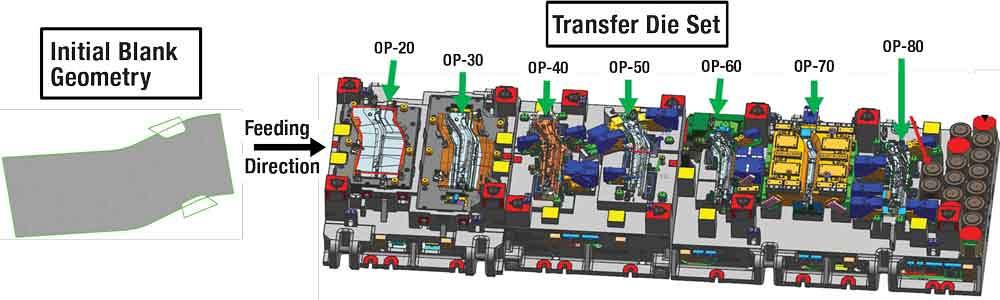
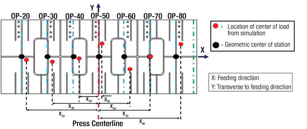
Researchers at The Ohio State University’s Center for Precision Forming studied a part provided by Bowman Precision Tooling. The transfer die set for forming this part was about 6,000 by 1,700 millimeters, comprising seven individual dies (see Figure 2). The distance between the centers of each station was 800 mm.
The aim of this case study was to develop a methodology for predicting off-center loading in a transfer die set using a commercially available finite element (FE) software package (AutoForm R8 in this case), and to estimate the forces on the four columns of the press. The off-center loading calculation was done only at bottom dead center (BDC).
Develop a Methodology. The methodology developed through this case study involved five steps:
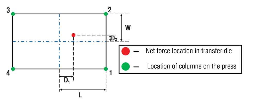
Estimate Forces. Researchers divided the net moment on the press by the net force (sum of forces on all stations) to obtain the distance of net force (D1 and D2 in Figure 5) from the press center. To calculate the forces on the four columns, the net force (F) and the value of distances (D1 and D2) can be substituted in the formulas below:
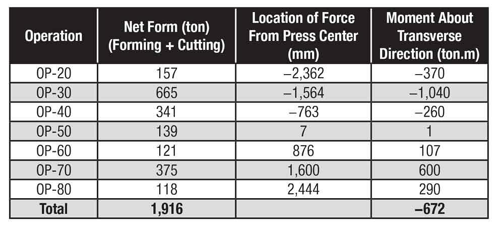
Figure 6 shows the calculated values of net force, force location from press center, and the moment produced by each station for this case study. To compensate for the moment produced by off-center loading, researchers installed 11 nitrogen cylinders, each producing 22 tons of force, at the extreme end of the transfer die set and balanced the press.
This methodology also can be used to predict off-center loading in a transfer die set for simulations developed in an alternative FE package, such as PAM-STAMP. AutoForm R8 has the capability to directly calculate the off-center loading in a progressive die.


The Fabricator is North America's leading magazine for the metal forming and fabricating industry. The magazine delivers the news, technical articles, and case histories that enable fabricators to do their jobs more efficiently. The Fabricator has served the industry since 1970.
start your free subscription
Easily access valuable industry resources now with full access to the digital edition of The Fabricator.

Easily access valuable industry resources now with full access to the digital edition of The Welder.

Easily access valuable industry resources now with full access to the digital edition of The Tube and Pipe Journal.

Easily access valuable industry resources now with full access to the digital edition of The Fabricator en Español.
Seth Feldman of Iowa-based Wertzbaugher Services joins The Fabricator Podcast to offer his take as a Gen Zer...


