


Press Brake Manager
Making heavy plate bending more efficient is about more than effectively moving material to and from the press brake. Positioning, measuring, and adjusting the workpiece also affects the stability and repeatability of bending.
For heavy metal fabricators using high-tonnage press brakes, the ratio of material handling time to forming time is astonishingly high. Making heavy plate bending more efficient is about more than effectively moving material to and from the press brake. Positioning, measuring, and adjusting the workpiece also affects the stability and repeatability of bending.
This is the reality for an increasing number of shops turning to press brakes of 400 tons or more to bend longer lengths of high-tensile-strength steels in pursuit of lower-weight structural components and lower cost-per-part manufacturing. Fortunately, a growing list of machine accessories and automation devices can lighten the load.
In many critical applications, material distortion is enemy No. 1 when it comes to part quality. The less distortion, the better the quality of the bend. One way to minimize distortion is to support your material better.
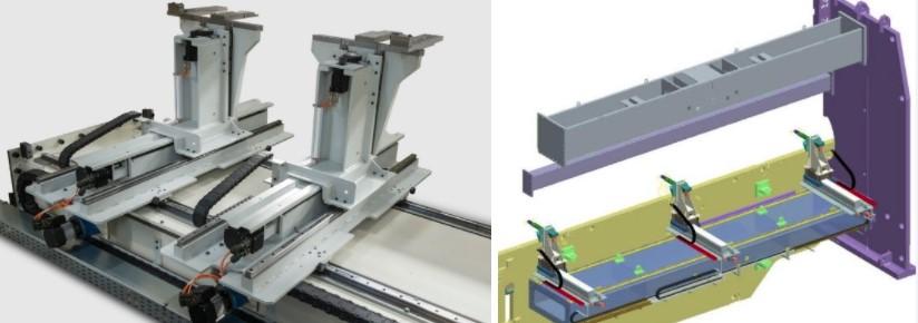
To keep the workpiece on an even course during bending, try using sheet supports. Placed in front of (and sometimes behind) the press brake, these devices reinforce the sheet during bending. The support arm makes full contact with the material, preventing material sagging (especially in thinner sheet). Heavy-duty followers can support large workpieces weighing up to several thousand pounds, depending on the make and model of the system. Supports can include a sheet follower at the front and rear of the machine and a fixed or movable follower in the middle of the machine.
The operator slides the supports into position and activates them via the machine controller. The sheet supports follow a synchronized process, knowing exactly the angle they need to follow and the speed of the machine. They can support the total width of the workpiece using two internal motors: one axis moves vertically and another one rotates or swivels.
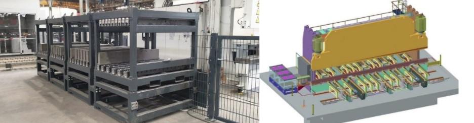
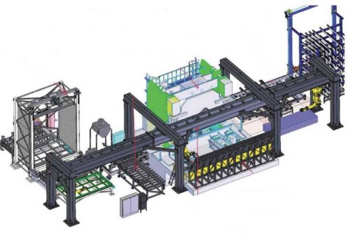
On extra-large press brakes, up to four T-axis sheet supports are not uncommon. The number of T axes depends on the length of the machine and the length, width, and weight of the workpiece. The 3,000-ton press brake in Figure 1 uses three heavy-duty material support devices adjustable in the front and at the back along the length of the machine. Together, they serve as a table support for handling plate.
Sheet followers can work in combination with a press brake’s adaptive bending system. Most press brake manufacturers offer both accessories, but often the devices work independently of each other. The most effective bending process uses the two accessories in concert to achieve repeatable accuracy.
Easy handling of the workpiece is extremely important. The easier it is to move the workpiece, the better assurance that you’ve gauged properly, which translates to better bend accuracy.
Large plate bending requires better material support at the front and back of the machine. In fact, it’s logical to have material support at the back of the machine, as it’s easier and much less labor-intensive to push material against a stop than to pull it. This is also a matter of operator safety. It’s best to have the plate moving away from the operator, pushing rather than pulling the material. Increasingly, high-tonnage press brakes have pusher gauges in the front and back of the machine as well as extractors to push parts outside of the machine to a transport line.
Once the material is positioned on the press brake, measuring, bending, and in-process control take up the story. To produce straight bends, high-tonnage, long-bed-length press brakes require a crowning system, which helps keep the bend angle consistent over the full length of the part. The longer the bed, the greater the machine deflection. And the higher the machine tonnage, the greater the need for deflection compensation.
FIGURE 1 Three heavy-duty followers are designed to support heavy material during forming
Deflection of the bed and ram under bending load is inherent to the bending process regardless of the press brake’s size or tonnage. Such deflection can cause an inconsistent bend angle along the part length, varying from the center to the ends. This distortion typically can be compensated for automatically with a single symmetrical, CNC crowning bed (V axis), a built-in feature of many high-tonnage press brakes.
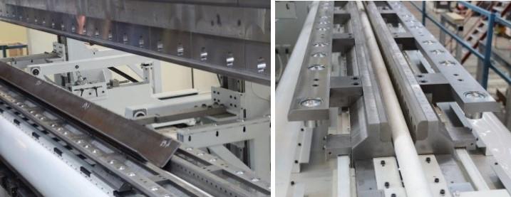
The dynamics change, though, when bending very long parts where bending errors from material variation can be seen, especially in nonsymmetrical part profiles. For these applications, smart crowning systems (see Figure 2) address variations in material thickness and material properties such as strain hardening, which can influence the bend angle result as well as the consistency of the bend angle over the part length.
In these systems, the CNC calculates for crowning and automatically compensates for deflection by moving a wedge unit. Located on top of the wedges are transversal adjusting segments, all individually activated by a dedicated hydraulic servo actuator. Each actuator receives a command from the CNC depending on the compensation required.
The system calculates the compensation requirement based on sheet thickness, sheet thickness variations, material variations, tool wear, and other factors identified by the adaptive bending system. The control displays each segment’s position graphically and calculates the necessary crowning based on the angle value obtained by the adaptive bending system.
Nowadays the vast majority of press brakes, no matter the tonnage, are sold with an adaptive bending system. An in-process angle monitoring system adapts the ram position in real time to achieve an accurate bend. This eliminates manual test bending and corrections. Scrap is reduced, and so is operator involvement. A true real-time angle measurement system, which should not increase cycle time significantly, provides feedback to the machine control for positioning of the ram to produce an accurate bend without secondary compensation.
Some applications use a combination of smart crowning, adaptive bending, and material followers. Such systems can be designed to compensate for significant material variations, handling even high-tensile-strength materials or those with high springback values of 30 or 40 degrees. Individual wedges are positioned to provide local adjustment at certain intervals across the bed length. The followers keep material in position, and the adaptive bending system measures and adjusts to create an accurate, repeatable bend.
Distortion also occurs when rotating, turning, lifting, and positioning the material.
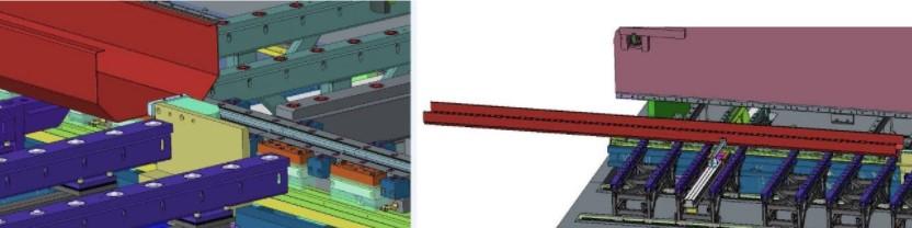
Having more points of gauging reference when bending larger or longer workpieces helps address issues stemming from material deformation or distortion. The hydraulic system and the crowning provide the correct bend angle, while the backgauge ensures that the correct size is produced. Increasingly, high-tonnage press brakes are being equipped with a modular backgauge (see Figure 3), often in 6- or 9-axis configurations with gauging references every 2.5 to 3.5 meters.
One advantage of a modular backgauge is that it offers a third stop. When material is pushed against two stops (the outer fingers), it’s difficult if not impossible for the operator to see material distortion such as bowing. Using three stops helps the operator spot the distortion easily. Adding a hydraulic cylinder in front of the machine to push the material against the backstop and middle backstop prevents distortion and helps form a straight, accurate angle.
Material handling on large press brakes poses an obvious safety risk, but so too does tooling setup and changeover. And, of course, improving the loading and unloading of large, heavy tools can greatly improve output.
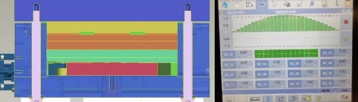
FIGURE 2 Smart crowning systems calculate the required crowning and automatically compensate for deflection.
Here a system called a tooling warehouse can help. This isn’t a literal warehouse but instead a tooling housing unit that connects to the press brake. It’s worth considering for fabricators that use a variety of punch radii and V-die openings as well as a variety of narrow tool segments. The more tooling that is available, the more flexible these operations can be.
Instead of changing out tools in the traditional way, operators simply slide punches and dies from the warehouse to the machine or vice versa. Using one finger, they can slide heavy sectionalized tooling in and out of the machine. The maximum length of each tool depends on the warehouse design.
Figure 4 shows a tooling warehouse system in which punches and dies are transferred to and from the machine using roller units. The system stores tools in rows that are 60 in. long and can hold up to 11 rows of punches and up to five or six rows of dies, depending on the die widths.
The warehouse also can be controlled by the CNC (see Figure 5). In fact, some CNC tooling warehouse systems can be designed to sit between two press brakes so it can feed punches and dies to both machines.
Another example of “tooling on the move” is the CNC V die, which can be especially helpful when forming long parts (see Figure 6). Constructed for heavy-duty applications, the CNC V die allows easy adjustment of the opening. With CNC V dies working in combination with the brake’s smart crowning system, the control identifies weak spots in the material and compensates to ensure bending accuracy.
Extraction devices can help. For instance, the setup in Figure 7 uses an extraction system to move long formed components off the machine. As the system works to extract the part, the operator positions the overhead crane to deliver the next plate to the press brake. Some applications use third-party material handling systems. One such system was designed with heavy-duty part manipulators that lift using compressed air. Designed to work with a range of industrial products, the manipulator balances the load and then lifts, moves, grips, turns, rotates, follows, and positions the workpiece. Operated manually, these simple systems—which can be integrated into the press itself—offer an efficient way to load material from a pallet to the brake. For heavy-part fabricators manufacturing a dedicated product, the objective is to keep the highest efficiency of process flow. This calls for a higher level of automation. One manufacturer of hydraulic cranes (see Figure 8), each made of high-strength steel, aimed to handle, position, and form crane arms with a high degree of accuracy at a lower cost. To that end, the company invested in a comprehensive, highly automated forming system. A robot transports the laser-cut blank from a warehouse storage unit to the front of a 1,000-ton press brake with a bending length of more than 20 ft. The automated system bends the plate at an average cycle time of 5 minutes. When formed, the piece is automatically extracted at the side of the press brake and is transported by a robot to a 3D scanning system for a quality control check, then on to a robotic welding station for final processing. FIGURE 3 Modular backgauges offer a third stop, which can help operators spot workpiece distortion. The press brake uses an advanced adaptive bending system. Its multiaxis modules position the workpiece and measure the angle. The digital information is relayed to the CNC, which automatically makes the necessary adjustments to the part and ram position to produce the correct profile. Variations do not accumulate but are instead compensated for in subsequent bend steps. The adaptive bending system adjusts in real time and automatically handles the workpiece via positioning modules. This turnkey operation is a stark contrast from the fabricator’s previous process, which required the use of gauges, traced bending lines, and manual manipulation of the workpiece using a bridge crane and lifting accessories. The new system improved part accuracy by 50%. Creating a more stable, repeatable forming process for heavy plate requires a big-picture approach. Material handling devices used before and after forming, smart crowning, in-process angle measurement and control, innovative backgauging, and other accessories, applied individually or together, change the bending trajectory from the risk of creating extraordinarily expensive scrap to the assurance of first-part-good-part accuracy. While these accessories require substantial investments, the ROI is immediate and significant: better process control, higher productivity, and improved safety.Efficiency of Flow
Weighing the Cost


The Fabricator is North America's leading magazine for the metal forming and fabricating industry. The magazine delivers the news, technical articles, and case histories that enable fabricators to do their jobs more efficiently. The Fabricator has served the industry since 1970.
start your free subscription
Easily access valuable industry resources now with full access to the digital edition of The Fabricator.

Easily access valuable industry resources now with full access to the digital edition of The Welder.

Easily access valuable industry resources now with full access to the digital edition of The Tube and Pipe Journal.

Easily access valuable industry resources now with full access to the digital edition of The Fabricator en Español.
In this episode of The Fabricator Podcast, Caleb Chamberlain, co-founder and CEO of OSH Cut, discusses his company’s...


