


Senior Editor
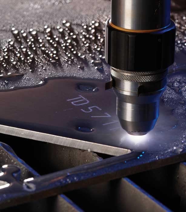
There’s something about a high-precision plasma-cut edge. It’s shiny, almost glassy, and the cut geometry keeps getting more precise—with minimal edge rounding and washout, perfectly square or close to it. Mechanized precision plasma cutting has come a long way.
Although approaches vary depending on the system, these technologies make a clean plasma-cut edge using similar ingredients: a plasma gas, a shielding gas, and a way to guide both in just the right way, at just the right pressure and energy level to create a cut as cleanly and economically as possible.
Conventional plasma cutting tends to leave a rounding top edge and edge angles that aren’t square. The edge also has pronounced lagging striations, with the torch “pulling” the plasma arc along.
The lag causes challenges for sharp corners, particularly in materials 0.5 inch thick and more. When the top of the arc makes a sharp turn, the lagging bottom of the arc is pulled around and ends up not following the cut path all the way to the corner—hence the corner rounding.
Cutting programs tell the torch to slow down before it reaches a corner geometry. For the best corners, technicians still resort to a looping cut path that shoots past the corner geometry and loops around to start the new cut line. This isn’t an option for internal features such as square, rectangular, and other polygon holes, which is why they remain perhaps the most challenging geometries for plasma to cut.
Another challenge with interior features like holes and slots involves dealing with the lead-in and lead-out of the cut, the area of overlap between where the arc enters and exits the workpiece profile. To avoid a slight amount of extra material on the edge, a technician programs the plasma head to cut slightly beyond where it started. This leaves a small area that’s essentially cut twice, which washes out a little more material compared to the rest of the kerf.
Precision plasma cutting has minimized these challenges through what could be considered a swirling gas flow ballet, with electrical resistance as its music.
The ballet’s opening act starts with the gas preflow. Within milliseconds, a preflow of gas in the torch body (usually nitrogen or air, which are relatively easy to ionize) primes the environment in the right pressure, location, and time. When the right flow conditions are met, a high-frequency arc jumps between the electrode and nozzle, which ionizes the gas.
This converts into a pilot arc between the electrode and the nozzle. The pressure rises, which pushes the pilot arc out of the nozzle bore and transfers onto the workpiece. Aiding the arc’s transfer to the plate is the level of electrical resistance, which is made less between the electrode and plate than between the electrode and nozzle. The current is then ramped up, and the second act begins: the dance between the plasma gas and the assist gas.
Ionized plasma gas creates the plasma, while shielding gas isolates it from the ambient air and helps dial in the quality of the cut edge. It does this using specific chemistries (gas mixtures), flow rates and pressures, as well as specific paths the gases take through the torch body to create a swirl upstream of the cut.
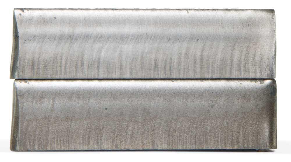
A 300-amp precision plasma system cut these two pieces of 0.75-in.-thick mild steel. The top part was cut with a new consumable set, while the bottom was cut with the same consumable set after about 1,400 cuts. Photo courtesy of Hypertherm Inc.
“In recent years we’ve perfected gas pressures and flows,” said Dirk Ott, vice president of global plasma automation for Thermal Dynamics, an ESAB company. “There are some approaches to mix gases, be it the plasma gas or shield gas, to improve the surface finish.”
“Air really can cut anything,” said Praveen Namburu, group lead, torches and consumables at Ladson, S.C.-based Kaliburn Inc., a Lincoln Electric Co. He added that an air plasma and shielding gas combination, while it may be economical, isn’t the most common choice for achieving high edge quality.
As industry sources explained, choosing the right gas combination for precision plasma starts with understanding how gas chemistry affects the cut. In carbon steel, oxygen induces an exothermic reaction that increases the cut speed; helps evacuate molten material; and creates a clean, square edge.
Most oxygen plasma cutting uses air assist gas, but pure oxygen shielding has its benefits on thin-gauge material as well as in some specialty holemaking applications. “Thicker steels may benefit to mix some nitrogen in the shielding,” said Ott. He added that this can be an air-nitrogen mixture or an oxygen-nitrogen mixture. “Particularly in the lead-out [of the cut], the washing out can be minimized when you use a shielding gas mixture. The small amount of oxygen smooths out the material at the end of the cut, better than when just using air.”
In stainless, nitrogen plasma gas generally works well for 0.375-in.-thick material and less. For materials less than 0.5 in. thick, a gas mixture like F5 (5 percent hydrogen, 95 percent nitrogen) can be effective.
Thicker stock also benefits from plasma gas with hydrogen content, like argon-hydrogen or argon-hydrogen-nitrogen mixtures. Hydrogen prevents the reaction of oxygen with the cut surface, resulting in a smooth, shiny appearance. This is why stainless steel cut edges benefit from mixtures like F5 and H35 (35 percent hydrogen and 65 percent argon) for the plasma gas, and nitrogen as the shielding gas. For systems with advanced mixing capabilities, higher levels of hydrogen in the plasma gas mixture are used to cut thick stainless steel.
“For aluminum cutting, nitrogen as a plasma gas with water as a shielding fluid results in an optimal cut, with a much smoother cut edge than with dry nitrogen or air shield gas,” said Soumya Mitra, plasma design engineer at Hypertherm, Hanover, N.H.
Specialized plasma-shielding gas mixtures abound. One plasma gas for nonferrous cutting is H17, which has 17.5 percent hydrogen, 32.5 percent argon, and 50 percent nitrogen. “This helps give you a lower arc temperature and narrower kerf,” said Namburu.
Some systems even use propane combined with nitrogen as an assist gas with a nitrogen plasma gas. Propane includes hydrogen, which again aids nonferrous cutting. “The hydrogen gives you the cleansing action on aluminum and stainless steel, almost like a bright annealing-type cutting process,” said Stephen St. Hilaire, plasma product manager at Komatsu America Industries LLC, Rolling Meadows, Ill.
A high-precision plasma arc process achieves higher amperes per square inch than achieved with conventional plasma. Manufacturers achieve this differently. Some constrict the arc and make it more effective with higher gas pressures, a smaller torch orifice, and/or a longer nozzle.
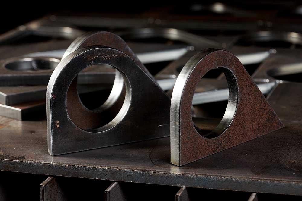
Hole and edge quality in precision plasma continues to get better. Photo courtesy of Kaliburn/Lincoln Electric Co.
Another way is to vent some gas out of the nozzle, which constricts the arc as it makes its way down the torch body to the nozzle bore. “This helps the arc achieve top-edge sharpness to the cut,” said Steve Liebold, plasma engineering team leader at Hypertherm Inc.
Plasma gas inside the torch body swirls downward, and, right before entering the cutting orifice, the outer, cooler layer of gas exits the torch. “What exits out the bore is the arc and only the gas that actually contributes to the cut,” said Mitra.
In some applications the shielding gas swirls as well. “Rotating the assist gas can produce higherspeed cutting with less slag or dross,” said St. Hilaire, adding that the concentricity between the nozzle and shield cap, which contains the channels for the shield gas rotation, is extremely tight.
The system works, St. Hilaire explained, because the swirl induces a pressure differential. Material naturally moves away from the high pressure on the cut edge to the low pressure on the scrap edge. The result: a tapered edge on the scrap side and a square, dross-free edge on the cut side. “The cut face is very smooth, from ¼ in. all the way to 1 in. The scrap edge has some bevel angle from 3 to 5 degrees, but the product cut face side is 0 to ±1.5 degrees.”
Some systems now are designed with torches that allow the shielding gas to impinge at closer to 38 degrees relative to the plasma arc. This increases the momentum of the arc along its axis while also impinging and constricting it.
“The design also affects where the impingement happens, farther away from the nozzle bore and closer to the top of the plate,” Liebold said. “It’s constricting the arc closer to where the cut is happening.”
He added that this system has a different, more axial plasma swirl, with the plasma gas flowing at a higher pressure. This makes the swirl ring in the torch look different; the holes are not drilled radially (which produces a radial swirl) but along the torch axis, enough to induce swirl action while allowing the pressure to drive the arc downward.
Liebold added that this wasn’t feasible before because of its potential effect on consumable life for mild steel cutting, especially regarding ramp-down errors, when the current and gas don’t ramp down in a controlled fashion. With the use of a valve behind the torch and a lower volume of gas inside the torch, new technology can detect the voltage attributes of the arc to prevent ramp-down errors.
Improved arc stability has helped improve performance when cutting geometries that present continual challenges for the plasma process. Liebold conceded that looping the torch path to cut outside corners still produces the best, sharpest edge with no noticeable radius. But for fine features and especially corners and cutouts with acute angles, arc stability has improved cut quality greatly.
Plasma’s hole-cutting capability is also progressing. In recent years some systems have used oxygen both as a plasma gas and shielding, allowing the exothermic reaction oxygen provides to smooth the edges of small holes, down to a 1-to-1 thickness-to-diameter ratio in some situations. Today systems can change accelerations and travel speeds as the torch makes its way around the hole circumference, generally starting slow and speeding up as the torch reaches the end of the cut path, where there is less material to remove.
Quality plasma-cut edges, such as these carbon steel samples, have a shiny, almost glassy look. Photo courtesy of ESAB.
“This really helps with the appearance of the bottom of the hole,” Liebold said, explaining that a faster speed induces less heat into the hole near the end of the cut path, which in turn helps keep a rounder shape at the bottom throughout the cut.
Edge quality hurdles remain for plasma cutting. For instance, try cutting a small hole in thick stainless steel, and you’ll likely see excessive dross hanging from the bottom of the cut. The process’s slow travel around a hole perimeter (compared to a straight cut) induces extra heat.
Sources added that new process technologies don’t change physics. Incorrect process parameters or poor machine motion will still lead to poor edge quality regardless of the plasma cutting power source and torch used.
All the same, new plasma technology, combined with motion control of lead-in and lead-outs of specific cuts (especially in holes), continues to improve. Height control has played a role too. The industry has moved away from constant voltage settings. As the electrode burns back over time, the torch standoff will be lower in order to maintain the same voltage, a change that hinders cut quality. So now systems with automatic height control, with a sample arc voltage protocol, maintain a constant distance between the tip and material surface, regulating the voltage for every cut.
Optimal motion control (an entire subject unto itself) also fits into the cut quality puzzle too. High-quality cutting cannot be accomplished without high-quality motion.
Ultimately, the right gas alone won’t do the trick; neither will an innovative flow of process gases or optimal process control. Instead, all of these together have helped produce plasma-cut edges so clean that they don’t look like they were cut with a thermal process at all.
Hypertherm Inc., 800-643-0030, www.hypertherm.com
Kaliburn Inc., a Lincoln Electric Co., 800-321-8072, www.lincolnelectric.com
Komatsu America Industries LLC, 800-707-2767, www.komatsuplasma.com
Thermal Dynamics, ESAB, 866-279-2628, www.thermal-dynamics.com


The Fabricator is North America's leading magazine for the metal forming and fabricating industry. The magazine delivers the news, technical articles, and case histories that enable fabricators to do their jobs more efficiently. The Fabricator has served the industry since 1970.
start your free subscription
Easily access valuable industry resources now with full access to the digital edition of The Fabricator.

Easily access valuable industry resources now with full access to the digital edition of The Welder.

Easily access valuable industry resources now with full access to the digital edition of The Tube and Pipe Journal.

Easily access valuable industry resources now with full access to the digital edition of The Fabricator en Español.
In this episode of The Fabricator Podcast, Caleb Chamberlain, co-founder and CEO of OSH Cut, discusses his company’s...


