


U.S. Operations Manager
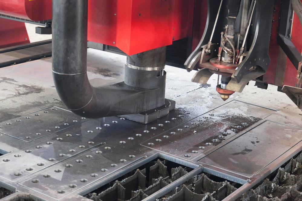
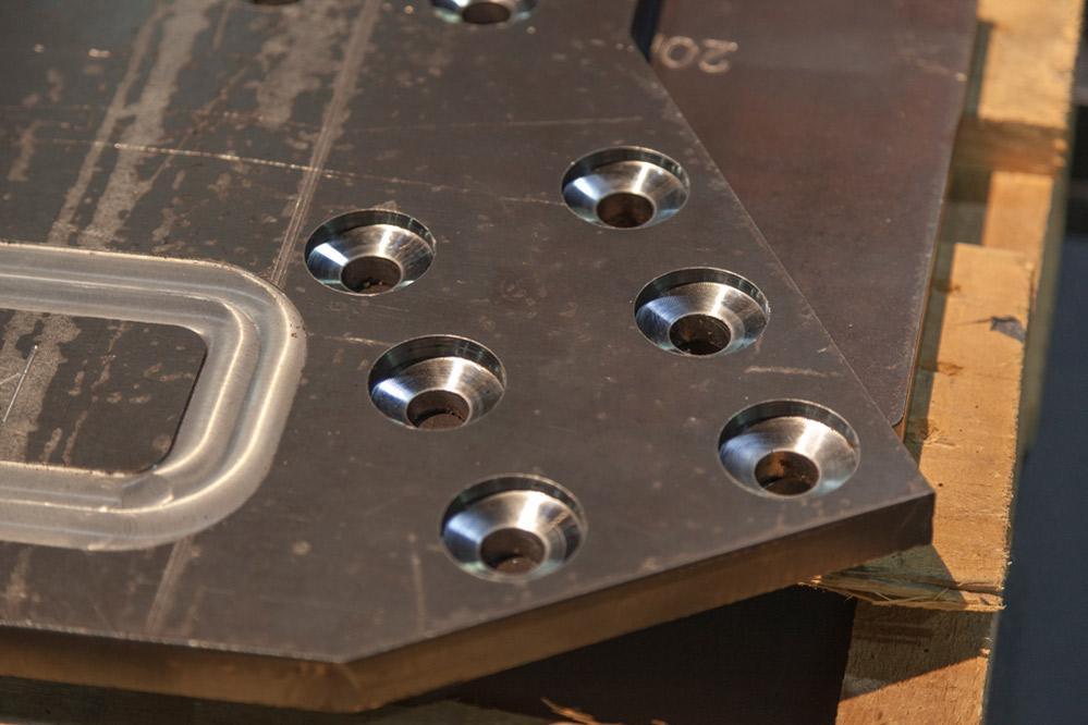
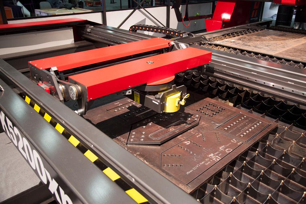
The drilling, chamfering, milling, tapping, and plasma cutting these workpieces required were all performed on one machine.
Photographers love rooster tails, those spark plumes a plasma torch makes as it starts to pierce thick plate—an iconic image of heavy industry getting to work. Anyone managing a heavy-plate cutting operation, though, could certainly do without them. Flashy rooster tails don’t show “America’s manufacturer getting the job done,” but instead shows plasma consumables wearing faster than they should. Shop managers like to see plasma torches cutting, not piercing. After all, cutting is where the money is made.
From this demand came the fabrication industry’s early combination plate cutting machines, those that had not only plasma and oxyfuel torches, but also hard tooling like drills and (more recently) mills. Introduced several decades ago, these plate cutting combo machines were developed to solve the piercing conundrum.
Today these systems have advanced to become plate cutting’s Swiss Army knife. In this sense, their main function has evolved. They’re now more than just about avoiding or minimizing the pierce, though it’s still an important variable in the overall equation. It’s now about minimizing handling, eliminating secondary operations, and increasing part flow velocity, from raw stock to the next application downstream.
At first these machines simply offered drilling capability alongside plasma and oxyfuel cutting. Instead of dealing with a lengthy pierce cycle that was hard on torch consumables, fabricators now could drill a pilot hole, then edge-start with the cutting torch.
This also opened up new nest layout possibilities, particularly in very heavy plate (such as 2 in. thick), in which a plasma pierce would be difficult, time-consuming, or just impossible. In these plates, programmers incorporated edge starts from the plate edge and perhaps some chain cutting from one part profile to the next, so the torch wouldn’t have to stop and repierce during the cut.
Of course, that edge-starting requirement limits the nest layout possibilities. A programmer might have to end up with a smaller remnant—so small that it might make sense to just cut it up for scrap rather than save it. An integrated drill frees the programmer to place pilot holes wherever needed to maintain an optimal, efficient, material-saving nest layout.
The drilling of pilot holes was a big reason behind the early successes of these combo machines, but it wasn’t the only reason. The ability to add drilled features was an added benefit. The machine could also add small holes with high depth-to-width ratios that were difficult or impossible for conventional plasma torches to achieve. Sometimes fabricators needed to cut larger holes that, because of their tight tolerances, required machining. And they needed holes of various sizes, some of them with tapped threads.
From this came combo machines with not only an oxyfuel and plasma torch, but also a cutting head with a rotating turret that held about a half-dozen tools. It could hold conventional twist drills of various sizes as well as tapping and similar cutting tools. Next came the demand for larger holes that, in turn, required larger drill bits on larger machines with high-horsepower spindles, now with through-spindle coolant delivery, to handle the increased torque and heat.
Chamfering and milling, including helical milling of pockets and slots, were the next logical steps. Consider a large cut part with an interior 8-in.-wide hole with extremely tight edge tolerances and a chamfer. Conventionally, the plasma would cut the profile, and the operator would then move the piece to a vertical machining center that would mill and chamfer the edge to the required tolerance.
This of course requires extra handling and setup time, which hinders throughput, so accomplishing it all in a single setup on a combo machine makes sense. And increasing throughput is the ultimate goal, particularly at a heavy fab operation in which cutting is the first operation in a routing. Problematic plate cutting can starve the rest of the shop. This ultimately is what those who have combination plate cutting machines aim to avoid.
Bevel cutting remains one of the most complex plasma arc cutting operations.
Of course, it’s not as straightforward as just adding a gantry carrying drills and mills onto a plasma cutting table. Milling and drilling large plate does abide by many of the speeds and feed conventions of machining, but in certain ways the process can be a different animal.
For instance, during drilling and milling of a workpiece fixtured in a vertical machining center (VMC), the part is fixtured in place, and the operator sets the tool length offset and work offset values. The machine knows where the workpiece is and where to start.
A small workpiece in a VMC is one thing; a 1-in.-thick plate spanning more than 15 feet wide or long is quite another.
When a heavy fabricator accepts plate material, the inventory manager or helper measures the plate thickness, and the operator loading material verifies it. Say it’s Grade 50 hot-rolled carbon steel. The combination plate cutting machine’s controller should have that material in its library, so it knows its average hardness, tensile values, and nominal thickness. What it doesn’t know is the actual thickness. A 1-in. plate that’s measured as 1.0625 in. is still within mill-spec tolerances. If the control doesn’t know the actual thickness, a drilling operation might not break through the bottom of the plate, and the operator just created rework.
Operators can change the plate thickness measurement manually in the control, of course, but this might not be adequate for every situation, particularly on a large plate. Just because a plate is 1.0625 in. in one place doesn’t mean it’s exactly that thick everywhere. Moreover, many plates bow. A drill or mill descending to 1-in. plate could find the plate surface to be a quarter inch higher or more, which can throw the entire operation off-kilter.
Effective workholding can help remedy these complications. Typical oxyfuel and plasma cutting operations don’t require workholding—it’s one of the benefits of using a “soft tool” thermal cutting process. But drilling and milling do. The mass of large plates might be heavy enough to withstand the torque from certain drilling or milling operations. But again, many plates received from the mill aren’t entirely flat.
Historically, combination machines have used pneumatic clamps. Some systems now use a servo-driven clamp foot—a small frame that descends directly below the spindle to clamp the work area and push it down flat. Once the workpiece is clamped, the system senses where exactly those clamps are in the Z direction, then adjusts the cutting program accordingly.
For precision work, combo machines need to cut in a strategic order that accounts for, among other things, thermal expansion. Say you have a nest layout that incorporates a series of blank profiles, each with a single hole in it. The position of the hole as it relates to the part perimeter is critical.
If the machine were to drill all those holes at once and then come back with the plasma torch to cut the profiles, the position of those holes likely would be off slightly, as measured from the part edge. Why? It has to do with thermal expansion. As the plasma cuts from one end of the plate to the other, the sheet “grows” ever so slightly, which in turn throws off the plasma torch’s position in relation to those holes.
To cut this sequence in a precise way, the machine uses a drilled hole as a datum point for referencing the profile; the machine switches to the plasma and makes the cut based on that reference. This process is repeated from part to part.
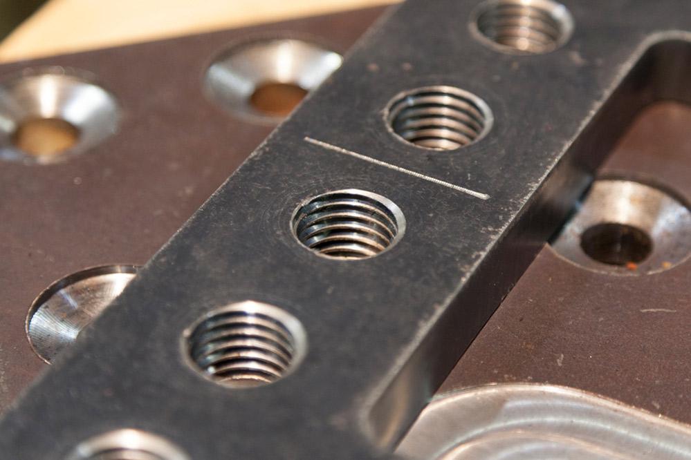
These parts involved a variety of milling and cutting processes, all performed on a combination plate cutting machine.
In this way, the system accounts for that thermal expansion. Sure, this is slower than doing plasma cutting all at once followed by drilling, but in precision work, such a cutting and drilling sequence wouldn’t reliably produce quality parts within tolerance. Regardless, it’s likely much faster, not to mention much less labor-intensive, than having to carry the work to a secondary drilling or machining operation.
Visit, say, a mine with a large rock chute and you’ll see a plow bolt sitting flush to a plate surface. Release the screw on the other side, lift out the large square bolt, and you’ll see a plow bolt hole that shows what a combination plate cutting machine can do in one setup.
Starting at the plate surface, the machine mills a shallow pocket to create a step offset, so the bolt sits slightly below the chute surface, protecting the bolt from excessive wear.
The end mill then plunges downward to machine a square pocket. After that comes the chamfering tool to create the 45-degree angle, which will help secure the bolt in place. The plasma then cuts a square hole through the plate.
This isn’t a simple operation. The mill plunges down a certain amount, removing only so much material; then comes the chamfering, then the plasma. How much material remains at the bottom of that hole? Based on that, what consumables would be best, and what speeds and feed rates would work best to achieve a truly square hole?
A novice operator probably shouldn’t attempt such an application. Most fabricators find long-term success in combo plate cutting when they ramp up application complexity gradually.
The example also illustrates that plasma cutting and milling and drilling both have their complexities. One isn’t fundamentally easier than the other, especially in the context of a combination plate cutting machine. Ultimately, a fabricator’s product mix drives the process complexity more than anything else.
Many fabricators tend to choose someone with machining experience to operate a combo plate cutting machine. This can make sense, especially if the product mix involves complex machining geometry. But if the product mix calls for simple holes but profile cutting with complex bevel geometries, a plasma cutting veteran could have valuable insights.
Beveling with a plasma can be very complicated procedurally. Every degree the plasma pivots from vertical, the material thickness changes and, with it, the plasma settings. Modern systems have the information they need to create an effective bevel, but the operator needs to follow the right procedure.
The torch itself has to start perfectly vertical; if it’s a little off, the bevel angle will be off, and so will the expected cut thickness and plasma settings. If, say, an operator cuts a beveled circle and yet the torch is at the wrong angle, that circle will turn into an egg shape.
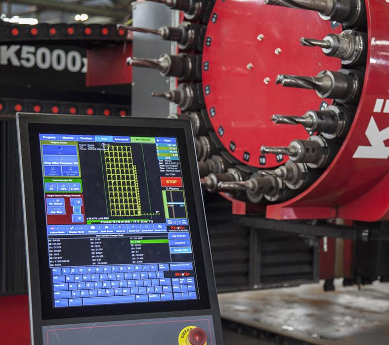
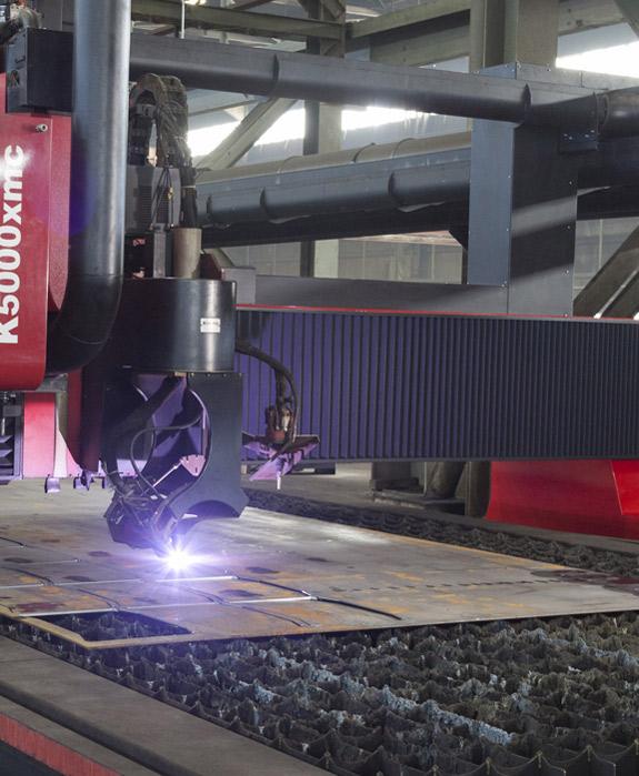
Along with their plasma and oxyfuel torches, today’s combo machines have a tool magazine that feeds a high-speed spindle with a variety of tools.
Regardless, when a fabricator is deciding who should run a combo plate cutting machine, the ultimate decision depends on the company culture, available talent, and training regimen.
An eager and engaged fabrication novice could operate a combo system, given the right training and enough time before ramping up to more complex work.
Combination systems work well for a variety of plate plasma cutting and machining applications—but not all plate machining applications. It goes back to the system’s clamping capability and the nature of plate material. Due to the nature of the rolling process, plates tend to be ever-so-slightly thicker in the middle. Because of this, a combo system really isn’t suited for surface milling. The machines perform well when milling pockets, relief holes, slots, and other shapes. But because of how the plate is held, along with the thickness variation, the combo machine’s end milling capability cannot create a surface tolerance that’s within umpteen places to the right of the decimal point.
That said, some fabricators have integrated a T-slot machining center right onto one end of a combo machine’s cutting table—essentially, a true machining center with its own tools, controller, and the clamping capabilities required. After the combo machine finishes the initial cutting, the critical parts are moved over to the machining table, where they can be clamped down flat for a true surface milling application.
Combination cutting really is about looking at the big picture, and this includes material handling. Say a combo machine finishes a nest of complex parts, milling, drilling, and plasma cutting the part profiles. Each part weighs about 600 pounds, so now operators need to wait for an overhead crane. And wait. And then wait some more.
Today certain combination systems come with heavy-duty pick-and-place automation. As a nest is complete, a robot with a magnetic end effector lifts each piece and stacks it on an adjacent pallet. The automation knows which parts it’s picking, so it can place them in a configuration that best suits part flow. For instance, if parts flow in kits, the robot stacks the cut blanks in kits. After parts are offloaded, the skeleton can be removed, usually via manual torch cutting.
This kind of automation shows what combination plate cutting is all about: reducing the number of times a part must be moved or handled. Ultimately, it’s about ensuring that the downstream constraint of the shop—be it in welding, forming, or anywhere else—is never starved for work. If a plate cutting process has a problem, and it causes a downstream constraint to operate at a lower capacity level, then a fabricator isn’t being as productive as it could be.
Jeff Lee is U.S. operations manager of Kinetic Cutting Systems, P.O. Box 652, West Burlington, IA 52655, 319-754-5040, www.kineticusa.com.

The Fabricator is North America's leading magazine for the metal forming and fabricating industry. The magazine delivers the news, technical articles, and case histories that enable fabricators to do their jobs more efficiently. The Fabricator has served the industry since 1970.
start your free subscription
Easily access valuable industry resources now with full access to the digital edition of The Fabricator.

Easily access valuable industry resources now with full access to the digital edition of The Welder.

Easily access valuable industry resources now with full access to the digital edition of The Tube and Pipe Journal.

Easily access valuable industry resources now with full access to the digital edition of The Fabricator en Español.
In this episode of The Fabricator Podcast, Caleb Chamberlain, co-founder and CEO of OSH Cut, discusses his company’s...


