


Applications Engineer, Fabrication Products

Figure 1
When cutting material thicker than 0.25 in., the punching option shouldn’t be ignored. Modern mechanical punch presses can work with material up to 0.375 in. thick.
Turret punch presses have come a long way over the decades. They progressed from the mechanical to the hydraulic to the electric servo drives introduced in the 1990s.
Servo-electric machines dominate much of today’s punch press market. But what if you’re processing carbon steel between 0.25 and 0.375 inch thick? You could call this thickness range “thin plate.”
Servo-electric machines usually are rated up to only about 33 tons of punching force. When you’re punching 0.375 in., you move beyond the capacities of the electric servo punch press. It is here that the modern mechanical punch press fills a need.
Cutting options abound in this thickness range. A CNC high-density plasma table with 130 amps of power generally can cut 0.25-in.-thick steel at 150 in.per minute (IPM), 0.375 in. at 110 IPM.
A laser, be it fiber or CO2, is another option, particularly if you’re cutting a lot of parts with a lot of contours. Lasers have so many power options that it’s difficult to quote a specific speed in a specific material. Regardless, if you process a lot of thin material, it may well be that, for your applications at least, nothing can beat a fiber laser’s speed. But as you cut thicker stock, the speed advantage isn’t quite as obvious.
Speed isn’t the only factor to consider. If you process precision parts sensitive to heat-affected zones, a waterjet is another option. You can expect a waterjet to cut at about 13 to 20 IPM on 0.25-in. material and at about 6 to 9 IPM on 0.375-in.-thick material, depending on the machine you have.
If you’re planning to punch a steady diet of 0.25-in.-thick material, choose the press wisely, especially if you want your machine to last. Push the envelope of your machine’s rated capability, and the machine almost surely won’t last as long as expected. And if you’re punching in the realm of 0.375 in., you’ll need a punch machine with 45 to 50 tons of punching force, something only a hydraulic or mechanical punch press can offer.
Servo-electric drive systems have become popular for good reason: They’re extremely efficient. Some modern electronic servo-driven machines are rated up to 30 tons of force (able to punch up to about 0.25-in. material) and produce two hits with every complete revolution of the servo motor—one during 0 to 180 degrees of rotation, and the other from 180 to 360 degrees. The energy for the first hit comes from a pushing force, while the second hit comes from a pulling force.
Electronic servo-driven machines adjust their stroke based on the material and the tool in use, and they excel at forming. You can adjust the bottom dead center (BDC) of the tool’s stroke to control the height of the form.
Note that you can still use form tools on a mechanical punch press. However, you do need to shim the tool to ensure you achieve the desired stroke depth for the form, test it, and record the settings in the setup log. If you don’t record the amount of shimming needed, you will need to test again when the job comes up next, which takes time and cuts into profits.
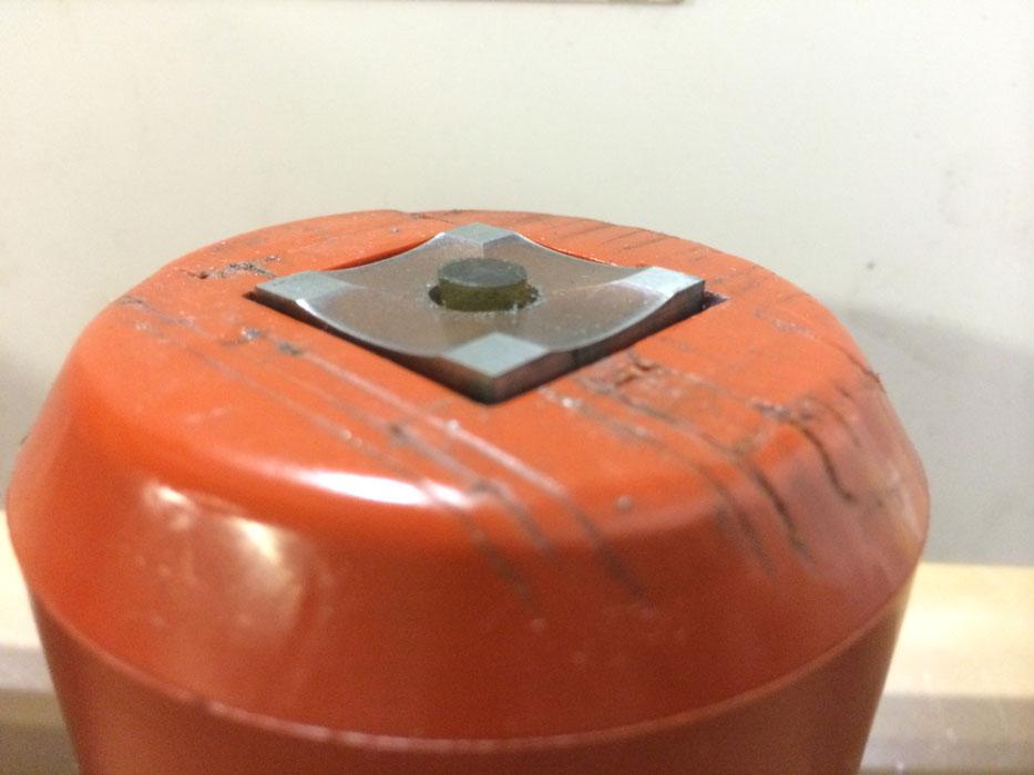
Figure 2
This shear punch can penetrate material with lower tonnage requirements. But it should never be used to bring a job within tonnage limits. As the edges wear, it essentially turns into a flat-bottom punch, which raises punching tonnage.
But if you’re working with 0.25- to 0.375-in.-thick material, it’s highly unlikely you’re making knockouts or forming louvers for air flow. If an enclosure with such thick material needs air flow, it probably has obround or circular holes or other kinds of openings. All these can be made in the mechanical punch press.
On your workbench or desk, find a pen with a clip that attaches to your shirt pocket. Hold the pen lengthwise, parallel to the table with the clip pointing straight up. That clip represents the eccentric of your crank shaft on the old-style punch machines. As you rotate the pen in your fingers, the clip is at the bottom of its stroke; this would be when the punch is through the material. On your machine, the flywheel engages the crankshaft to start rotating. When the eccentric mechanism is on top, the punch is at top dead center (TDC), after which it will rotate to the bottom.
Modern mechanical punch presses (see Figure 1) operate in largely the same fashion, except for a few key differences, the primary one being a modern control system. The punch press may be mechanical, but it’s still controlled electronically by a TDC controller, a permanent feedback system on the ram axis that ensures the system always knows where the ram is.
When the punch contacts the material, and the punch and die perform the initial cutting, the throat of the frame—be it a C-, J-, or bridge-frame machine—opens slightly. During this time, actual cutting occurs. If you were to look at the punched edge under a microscope, you’d see shiny portions at the top and bottom and a jagged edge in the middle. This is where the machine overcomes the material’s shear strength and the punch rips or bursts through.
With this stroke of the punch, all the rules of thumb we’ve been taught about punching come into play, including the clearance requirements between the punch and die, along with the punching tonnage calculations as published by your machine and tooling manufacturer. The higher the material’s shear strength (as with, say, stainless), the smaller punch perimeter you’ll be able to use to stay within the machine’s tonnage limits.
You need to balance this with your punch diameter requirements. From a tonnage perspective, you should never punch through material with a punch diameter that’s less than the material thickness. Any smaller and you end up defying the laws of physics, and your punch is bound to break.
The smaller the punch, the more force goes into a small area. It’s a little like over-sharpening your pencil. Push down on a dull pencil point on a table, and it will take considerable force to break it. Push down on a very sharp pencil, and within seconds the sharp point breaks.
When nibbling with punches, you should never have less than two times the material thickness under the punch. To do so could cause side-loading of your tools. Nibbling with a pitch less than the material thickness is like putting a power drill right on the edge of a piece of material. Pull the trigger, and it will walk right off the edge; before you know it, you’ll have tool wear because of side loading.
Also watch for edge quality problems when nibbling. Whenever you punch large holes with a round punch, you will have scalloped edges, which can become especially apparent when punching thick stock. If you’re using a punch with shear, the scalloped edge will be more pronounced and might not be acceptable. To minimize this, you should use a flat-bottom punch. The downside is that this will require full blanking pressure, because you’re using the full bearing surface of the tool. The upside is that the flat-bottom approach will eliminate the heavier scallop you would receive from a punch with shear.
If scalloped edges are acceptable, using a punch with shear can certainly be a good approach, and it can lower the punching force. Still, it’s never a good practice to use the shear of the punch just to bring the tonnage of the hit within the limitations of the machine (see Figure 2).
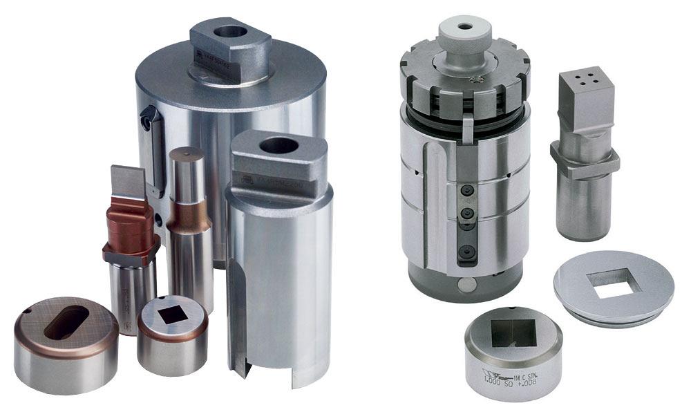
Figure 3
Push/pull-style tooling features a T-slot that secures it to punch machines that can accept this style of tooling. Although push/pull-style tooling can come with or without a spring pack, it is not thin turret tooling, nor is it thick turret tooling. Push/pull tooling, also known as 112 or 114 tooling, is well-suited for heavy-duty punching.
Here’s why. Over time the tooling surfaces wear and require sharpening. If the shear on the punch is not maintained, tonnage force gradually increases until eventually you end up with a flat-bottomed punch—which, again, requires full blanking pressure to burst through the material. If this exceeds the tonnage rating of your machine, major troubles will undoubtedly ensue. You could damage your tools and your machine and create an unsafe environment for your operators. That’s a high price to pay for improper tooling maintenance.
Punching thick material with spring-style tools, commonly called thick-turret tooling, can present a challenge. In this style of tool, the punch holder assembly has a spring pack on top of the toolholder. Stripping of the material is totally dependent on the spring pack to pull the punch out of the material.
After the initial punching force, these tools rely on springback force from the top of the holder to bring them back to the full up position and guarantee stripping. If the springs fail or become weak, then stripping does not take place. If the process is monitored, you’ll see a “strip miss detect” alarm on your controller. If it’s not monitored, your sheet may be pulled out of the work holders, or the punch may break.
Using the push/pull tools in mechanical machines, the punch holders do not require springs to return the punch to TDC because they are pulled up by the T-slot in the ram—hence the term “push/pull” (see Figure 3). This tooling style also is called 112 and 114 tooling. Each has a T-slot, and rams in machines that accept these tools have corresponding T-slot pockets. These tools can incorporate a urethane stripper, which for most applications would work fine, but they also can use a spring-loaded steel stripper when the demand for more reliable stripping is required.
Push/pull tooling allows the machine to push the tools into the material and pull them out. As the punch is pulled from BDC, the stripper will physically push the material off the punch tip. Whether the stripper is urethane or steel, stripping is going to take place.
When punching thick material, slug pulling usually isn’t a problem; gravity works to the process’s advantage. But in many other cases, you need to accommodate for physical realities when punching 0.25-in.-thick material and beyond, and this includes material handling.
When punching thin material, you have many part removal and handling options. You can go the conventional route and microtab parts in place, to be shook out later, or you could use specialty tools like V-line punches and dies that put a groove in the material. That groove allows parts to be hand-bent, eliminating a downstream forming operation. Parts also can be snapped apart, revealing an edge that requires no deburring.
With stock that’s 14 gauge and thicker, though, you’ll likely need to resort to traditional microtabbing—and you need to make sure those tabs are sufficiently narrow and of the right number for each part. If you have 0.375-in.-thick material with two 0.010-in. tabs on the corners of your parts, you don’t have a shake-and-break sheet; you have a bang-and-break sheet. Removing those parts will be difficult, to put it mildly.
You need to ensure you have tabs in enough places to hold the piece in place during the punching cycle, but you also need the tabs to be thin and sparse enough so material handlers can break out the parts efficiently. Determining the optimal tab size for your product comes from experience, and it is dependent on the sharpness of the tools and the tool radius. For instance, a rectangular part with sharp corners will require a different tab than a rectangle with radius corners. A common practice for using square and rectangle punches in thicker material is to add a small radius (0.010 in.) to the tools, so they don’t crack in the corners.
Heavy-duty punching machines should have heavy-duty work holders in good working order, with multiple clamps exerting significant force (see Figure 4). This allows the machine to manipulate plate up to about 440 pounds, depending on the machine model you have. If a plate exceeds this, you can slow the material traverse speed. Of course, if you’re punching such large sheet or plate, you won’t be breaking any speed records anyway. You should also lubricate the sheet, use heavy-duty tooling, and possibly use punches with additional back taper.

Figure 4
Work holders in good working order on high-tonnage mechanical punch presses should be able to manipulate heavy sheets (or thin plate) efficiently and accurately.
If your operation cuts lots of contoured parts from thin material, laser cutting (probably fiber laser cutting) likely will be the way to go. If your jobs consist primarily of straight edges, a punch press still can be very effective. And if you have both straight edges and contours, a laser/punch combination might be suitable, but it’s not your only option—especially when you get to thicker material.
Punch/plasma combination systems are available as well. As with a punch/laser combination, a punch/plasma system performs each operation sequentially, first punching and then high-density plasma cutting. An added benefit: A punch/plasma system costs less than its punch/laser combination cousin.
Determining the best machine for the job should always hinge on the application and the return on investment you need. An operation may well benefit from a powerful laser able to slice cleanly and quickly through a variety of materials. But if your application requirements include a nest of simple holes, slots, and lines, punching could be just as effective. And if you process thin plate (0.25 to 0.375 in. thick), it’s highly unlikely that cutting is the constraint operation anyway.
The bottom line: When it comes to processing plate 0.375 in. and less, punching is an option that shouldn’t be ignored.
Dennis Niesborella is applications engineer, fabrication products, Murata Machinery USA Inc., 2120 Queen City Drive, Charlotte, NC 28208, 888-846-1428, www.muratec-usa.com.

The Fabricator is North America's leading magazine for the metal forming and fabricating industry. The magazine delivers the news, technical articles, and case histories that enable fabricators to do their jobs more efficiently. The Fabricator has served the industry since 1970.
start your free subscription
Easily access valuable industry resources now with full access to the digital edition of The Fabricator.

Easily access valuable industry resources now with full access to the digital edition of The Welder.

Easily access valuable industry resources now with full access to the digital edition of The Tube and Pipe Journal.

Easily access valuable industry resources now with full access to the digital edition of The Fabricator en Español.
Seth Feldman of Iowa-based Wertzbaugher Services joins The Fabricator Podcast to offer his take as a Gen Zer...


