Editor-in-Chief
- FMA
- The Fabricator
- FABTECH
- Canadian Metalworking
Categories
- Additive Manufacturing
- Aluminum Welding
- Arc Welding
- Assembly and Joining
- Automation and Robotics
- Bending and Forming
- Consumables
- Cutting and Weld Prep
- Electric Vehicles
- En Español
- Finishing
- Hydroforming
- Laser Cutting
- Laser Welding
- Machining
- Manufacturing Software
- Materials Handling
- Metals/Materials
- Oxyfuel Cutting
- Plasma Cutting
- Power Tools
- Punching and Other Holemaking
- Roll Forming
- Safety
- Sawing
- Shearing
- Shop Management
- Testing and Measuring
- Tube and Pipe Fabrication
- Tube and Pipe Production
- Waterjet Cutting
Industry Directory
Webcasts
Podcasts
FAB 40
Advertise
Subscribe
Account Login
Search
A 3-D CAD modeling case study: When DFM imperils industrial design
The CAD jockey heard what the client wanted, but did he listen?
- By Dan Davis
- June 12, 2018
- Article
- Shop Management
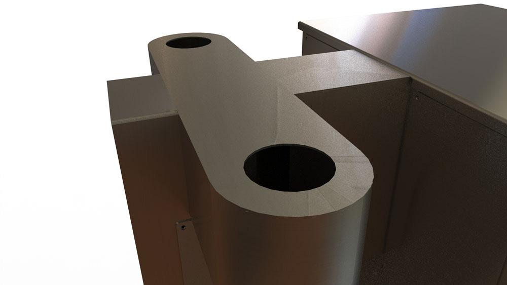
Figure 1a
This is a screen shot of the 3-D STEP file that was based on the industrial designers’ concept for the top of the coffee machine.
Disclaimer: This case study of a coffee maker’s sheet metal cabinet features a pair of inventors doing their best without the benefit of experience in manufacturing.
The previous edition of this column (“What the prototype reveals,” Precision Matters, The FABRICATOR®, May 2018, p. 40) showed how industrial design (ID) became reality. That reality included difficulty with fit and function.
To summarize the story so far, Figures 1a, 1b, and 1c show what happens when the contract for manufacturing includes these instructions: “Manufacturer to use best judgment and best practices in fabrication.”
Figure 1a shows the STEP file as provided to the fabricator. Figure 1b shows what the welding crew delivered. This model demonstrates excellent fit and finish. In the fabricator’s judgment, the best way to do this was to weld the top deck in place. Sadly, this great finish is not functional.
Figure 1c is a photo of the demo machine during assembly. The removable top cover makes assembly and plumbing possible.
Yes, the cabinet shown in Figure 1b was scrapped. The fabricator’s best judgment was not bad; it was not well-informed. This problem extended into required access and mounting for electronics. A well-made but incomplete design resulted in significant rework and make-do.
This demo machine featured self-tapping screws, liberal use of zip ties, and a fair amount of duct tape. In terms of design for manufacturability (DFM), it was not ready for commercial release.
The industrial design (ID) was pleasing within its area of responsibility—the cabinet’s external appearance. To its credit, the fabrication department did their best to follow the STEP file for fabrication. Sadly, the information it needed was being developed while the cabinet was being welded.
Execution of the Business Plan
The first stage of the business plan had required presentation of a working machine at a tradeshow. As rushed and inefficient as that operational mockup was, it was exactly what the budget and schedule allowed.
The sheet metal cabinet in Figure 1c may seem to be mostly accidental, but it was a success. Now a crowd of people wanted it to become real.
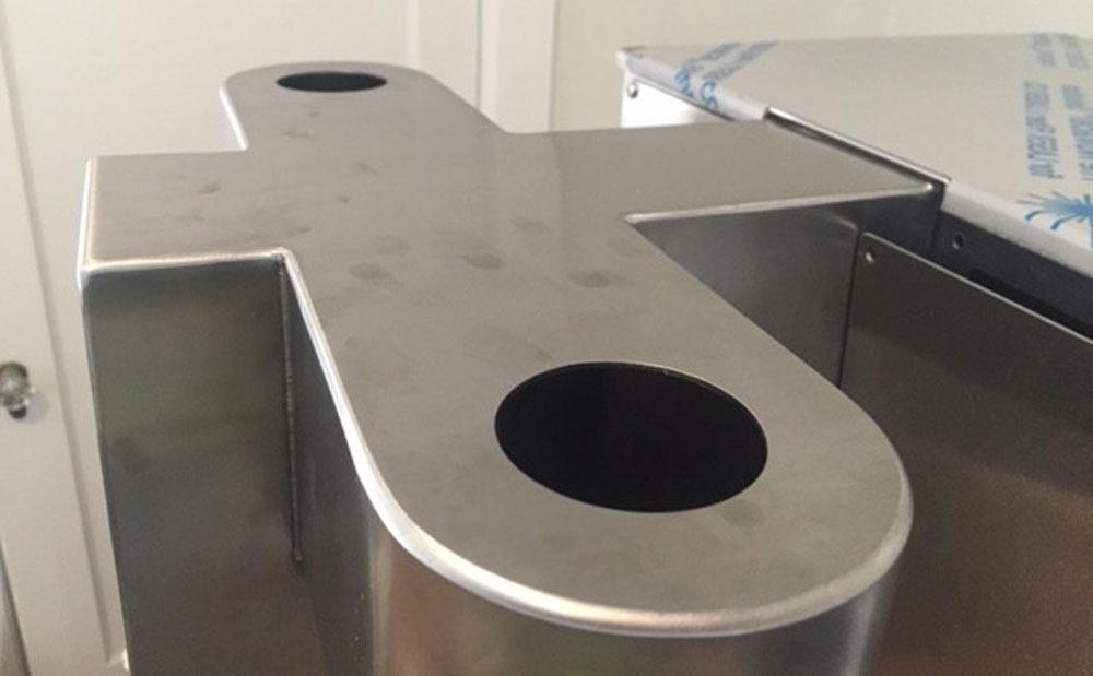
Figure 1b
This photo shows the best judgment of the fabricator based on the STEP file in Figure 1a. This was a fine job of precision gas tungsten arc welding and grinding.
Its manufacturing plan had gaps, but the business plan was on track and was now funded. The next stage in the plan called for the production of a small batch of coffee brewing machines for installation and stress testing.
Information Versus Communication
I was recruited to help correct the problems with the sheet metal design. Over time I did a professional job of producing a “buildable” design with excellent drawings for purchasing, fabrication, and assembly. My arrogance delayed that success, however. I did what I thought to be important: I helped with the ID instead of just DFM’ing what was in front of me.
What I understood at the start was that I was an expert in DFM. Thousands of drawings and hundreds of products have passed from my mouse. I also boldly wear the industrial designer’s hat. I say “bold” because I have very little formal training in ergonomics.
While tooting my horn as a CAD jockey, I chant about 40-plus years of applied study and practice in the precision fabrication trade. In a huff, I can call upon a vast reservoir of ego. This project trained me to be cautious with my self-certainty.
What they asked was , “Gerald, we have an excellent industrial design, but the prototype has some problems. Can you help us sort out the sheet metal?” What I heard was, “Gerald, we don’t have a clue about fabrication or design, so fix any problem you can imagine.”
The Trapezoid Side Step in Hindsight
My customer “laughed” to see such fun as my DFM ran away with the ID (see Figure 2). The model on the left is the tradeshow version. The right-hand CAD model shows roughly two weeks of a mouse that is off target. We know that with the benefit of hindsight.
At the time my design was informed by a clear understanding of what components needed to mount and where they should be located. A major problem that I corrected was the fit of the baskets that slide into the machine. The baskets had been compromised for the tradeshow. They wouldn’t go into the cabinet otherwise.
Most of the “wet” components had worked for the demo. I was pleased that I was able to retain much of the original ID. This included the glass bottles, control tablet, brewing mechanism, thermal carafes, and legs.
From the DFM point of view, the cabinet top required a great deal of labor to achieve a beautiful Class A finish; please recall Figure 1c. My improved DFM changed the shape of the top from a complex “T” to a simple box with corner radii.
While I was at it, I remounted all of the electronics and plumbing so they were hidden behind rear service panels—no screws visible from the front of the machine.
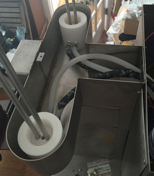
Figure 1c
After the cabinet in Figure 1b was scrapped and a new set of drawings were made, the top cover cabinet is made to be removable instead of welded in place.
Thinking myself clever, I added large vertical radii to corners to make the machine easier to wipe clean. I wasn’t entirely certain how to fabricate it, but a beaded flange around the top lid seemed like a good way to “cork” the top of the cabinet. My idea was to echo the theme of a metal coffee can lid.
Woodshed Nigh
In the next installment, the original industrial designers review how well I did in honoring their contribution. Hint: Service doors located on the back of the machine are a really bad idea.
The cabinet-by-Gerald in Figure 1c has yet to see the light of production; it is nonetheless an active design plan and Voga cherishes it. We discourage you from trying to compete with Voga’s patented brewer.
- Meet immediate business goals.
- Develop supply chain relationships.
- Prepare for continuous improvement.
As an example of recommended CAD behavior and design practice, the trapezoid model shown in Figure 2 was modeled as a rapidly extruded multibody part. Once I understood how big the cabinet had to be, I went as fast as I could to model the exterior appearance. This quick-but-dirty model resembles sheet metal but is not able to “unfold” and has no product manufacturing information, such as part number, revision number, and description.
Very few internal components are represented. All that mattered in this CAD model was visualization. My intention was to hand the lovely and DFM-friendly model back to the ID team to let them adjust it a little bit if needed.
Gerald would love for you to send him your comments and questions. You are not alone, and the problems you face often are shared by others. Please send your questions and comments to dand@thefabricator.com.
About the Author

Dan Davis
2135 Point Blvd.
Elgin, IL 60123
815-227-8281
Dan Davis is editor-in-chief of The Fabricator, the industry's most widely circulated metal fabricating magazine, and its sister publications, The Tube & Pipe Journal and The Welder. He has been with the publications since April 2002.
subscribe now

The Fabricator is North America's leading magazine for the metal forming and fabricating industry. The magazine delivers the news, technical articles, and case histories that enable fabricators to do their jobs more efficiently. The Fabricator has served the industry since 1970.
start your free subscription- Stay connected from anywhere

Easily access valuable industry resources now with full access to the digital edition of The Fabricator.

Easily access valuable industry resources now with full access to the digital edition of The Welder.

Easily access valuable industry resources now with full access to the digital edition of The Tube and Pipe Journal.
- Podcasting
- Podcast:
- The Fabricator Podcast
- Published:
- 04/30/2024
- Running Time:
- 53:00
Seth Feldman of Iowa-based Wertzbaugher Services joins The Fabricator Podcast to offer his take as a Gen Zer...
- Industry Events
Pipe and Tube Conference
- May 21 - 22, 2024
- Omaha, NE
World-Class Roll Forming Workshop
- June 5 - 6, 2024
- Louisville, KY
Advanced Laser Application Workshop
- June 25 - 27, 2024
- Novi, MI
Precision Press Brake Certificate Course
- July 31 - August 1, 2024
- Elgin,

