


General Manager
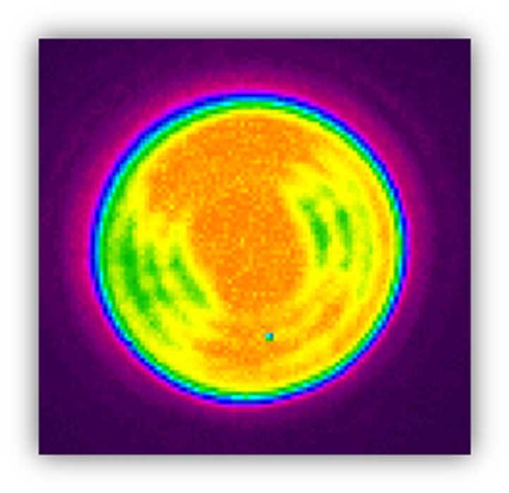
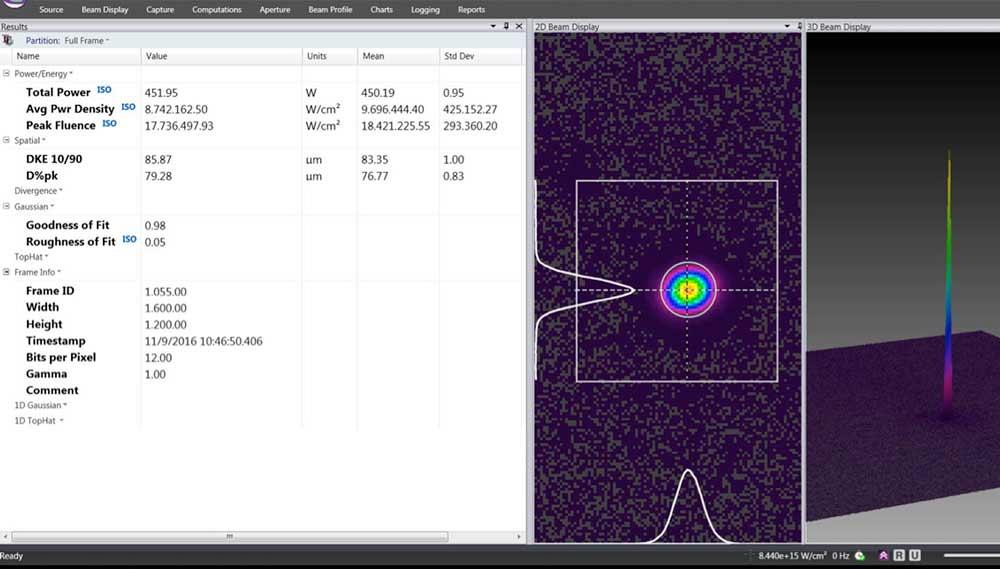
Figure 1
The laser beam profile shows the distribution of the beam power at the focus spot.
The laser has transformed metal manufacturing. Laser cutting has become ubiquitous, used by the largest OEMs and the smallest metal fabrication job shops. Laser welding has become a mature technology, central to many of the joining advances seen in industries like automotive and aerospace.
The laser also has been central to additive manufacturing (AM). This includes laser metal deposition, as used in the two major categories of metal AM, directed energy deposition (DED) and powder bed fusion (PBF). AM has restructured prototyping and development, promoted advanced designs, and is considered by many to be the future of manufacturing.
The laser has been driving metal manufacturing forward for decades, and it continues to do so. But to work correctly and predictably, the beam must be refined for the application. The beam’s properties, including its power, power density, and focus spot, all play a role.
Still, it’s difficult to understand what exact role these and other variables play, and how each variable relates to another in a specific application, without accurate measurement of the laser process itself.
Every manufacturing process involving a laser requires balancing the right laser variables with the right processing characteristics. 3-D metal printing illustrates this concept well. To print a metal part, metal powder is drawn on the build area to an exact thickness, while a focused laser beam heats the metal powder to the correct temperature; this fuses the powder.
If the laser power is too low or not applied long enough, the grains of powder do not melt properly; the metal becomes porous and, therefore, weaker.
If too much laser power is used or the laser is applied longer than necessary, the laser will drill into the fused powder, reducing the density of the structure. If the focus spot location is before or behind the build plane, or the distribution of the laser power is not optimized, inadequate melting of the metal powder will result. All of these conditions leave a part that is not metallurgically correct.
Power density is a measure of how the laser is applied to the material being processed. It is expressed as watts per centimeter squared—W/cm2, where watts is a unit of the laser power and centimeter squared is the area that relates to the size of the beam.
Expressed another way, a laser’s power density is the amount of power that’s concentrated down to a certain space. For example, a 400-W laser focused to a 50-micron-diameter spot size will yield a power density of approximately 41 megawatts per square centimeter.
In AM, a laser beam’s power density can exceed 1 MW/cm2, hence the need for accurate measurement. Dirty or damaged optics can distort the beam profile severely and can cause errors in power management.
The power density that the laser yields determines how exactly the laser interacts with the material and the results of that interaction. Ablating plastic, for instance, requires a much lower power density than cutting 1-inch-thick steel, because the two materials interact with the laser beam differently.
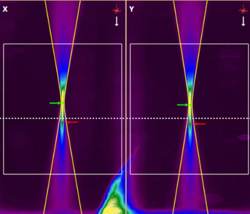
Figure 2
This result from a Rayleigh scatter measurement shows how the focus spot shifts. The laser beam focus spot has shifted from the red arrow, where the spot was at the beginning of the process, to the green arrow.
Laser power and beam size can change over time for many reasons. Most changes relate somehow to the second law of thermodynamics. A change in laser power or beam size alters the way that the laser interacts with the material—that is, the power density. When the power density changes, the laser system no longer processes the material as it was designed to do. This can lead to thermal effects and component degradation.
In AM, because power densities can exceed 1 MW/cm2, technicians must take great care to accurately measure the working laser beam. Dirty or damaged optics can severely distort the beam profile and may also cause errors in power measurement.
Laser beam focus spot size directly affects powder density (see Figure 1).
Good measurement ensures that a spot size is maintained within a finite window, allowing for a consistent, stable, and correct laser power density.
Focus shift in the Z direction (perpendicular to the work) is caused by thermal effects on the laser’s components: specifically, transmissive optics such as focusing lenses and protective cover slides. As the focus shifts, the spot size changes, which in turn changes the power density. This alters the way the laser interacts with the material.
Laser quality has increased greatly over the years. The cost of ownership and required maintenance have decreased. But lasers are more than light. The systems producing the beam are still made of physical matter. Components degrade over time, get dirty, and sometimes catastrophically fail. Performance drifts, especially with high-power lasers.
Hence the need for meaningful laser parameter measurement. But which measurements can help solve these problems? Laser measurement technologies help technicians analyze laser power and the spatial distribution of that power within the laser beam.
Legacy approaches to power measurement include the power puck, which is placed under the beam. The beam gives a burst of power, the puck absorbs it, and the measured temperature increase is used to calculate the laser beam power. Modern power pucks are available for lasers up to 10 kW with very high power densities. The puck also must adapt for temperature effects, because the thermal behavior of the puck is not completely constant with temperature.
Regarding beam profiling, legacy systems include methods like acrylic mode burns and burn paper. Burn paper is a one-dimensional test. The resulting mark is either burned or not. All information on laser performance comes from how the power is shaped (or distributed) in the beam. And the laser beam itself is, of course, three-dimensional.
Moreover, burn paper is not dimensionally accurate. The burn happens only where there is enough power to burn; measuring it for useful information about power density is useless.
An acrylic mode burn leaves a 3-D emboss in a block of clear acrylic that reveals a beam’s spatial power distribution. But there’s a big problem with this technique: Acrylic mode burns require the burning of acrylic plastic, which produces carcinogenic fumes.
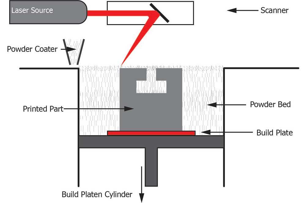
Figure 3
Modern laser measurement techniques in additive manufacturing measure the beam at the build plane, exactly where the laser interacts with the powder to build the part, layer by layer.
These and similar legacy measuring systems provide only single data points (no trending data), and interpreting them is subjective. This means that technicians make decisions based on incomplete analyses.
To truly understand the process parameters, technicians must know the power density profile of the laser beam. Total power, focus spot size, and focal plane location describe the working beam, but these parameters can change as beam delivery optics heat over time.
Modern laser measurement technologies try to understand these variables and attempt to constrain the variations. This helps to achieve consistently accurate constructs for good measurement.
To understand the delivered beam, technicians use beam profilers that employ a camera, scanning pinhole, or noncontact Rayleigh scatter (see Figure 2). These are NIST-traceable devices that can measure power density profiles against known standards. In short, they help technicians map and understand the delivered beam, allowing them to produce an analysis based on industry standards using immediate, live data.
Hybrid systems have sensors that measure the laser beam profile, power, and location. They provide an accurate picture of the beam’s power density profile as well as its location and consistency.
There are two approaches to laser measurement: in-process and at-process. In-process, or inline, measurement systems are integrated into the laser system and can therefore deliver a continuous analysis. They use a portion of the laser beam somewhere along the beam’s path, usually close to the object being processed, and can provide continuous, closed-loop feedback.
However, because of how this method samples the beam, it cannot analyze the entire system. Anything after the point of measurement is not part of the analysis. And, unfortunately, most laser system problems occur very close to the processing area.
At-process measurement provides complete measurement and analysis of the process, all at once. The beam is directed into the analysis system, which typically consists of a power measurement system, a beam profiling system, and a temporal pulse-shape measurement system. All work together to perform the entire analysis. The disadvantage to this approach, though, is that to set up and perform the analysis, technicians must take the laser out of production.
Some systems address both in-process and at-process requirements. They include both a CCD camera for spatial measurements and a separate sensor that measures the laser’s power density profile.
In an AM application, the camera is at the build plane (see Figure 3), so it can provide a power density profile right at the working laser beam—that is, right at the spot where the beam melts the powder and forms a layer of material. A beam splitter directs a small percentage of the beam to the camera, while most of the beam goes through the integrated power sensors (see Figure 4). These deliver information that helps build a single or multidimensional view of the spatial power distributions within the beam (see Figure 5).
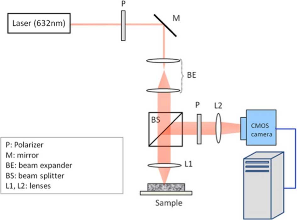
Figure 4
This measurement system uses a beam splitter that sends the beam to a camera for real-time measurement.
This arrangement can detect a change in the focus spot location, which in turn can change the system optics as the optics are heated by the beam. In AM, for instance, the focus location can move several millimeters over time, changing the beam’s effect on the metal powder. By measuring this shift in real time, technicians can correct for thermal shift before the damage is done.
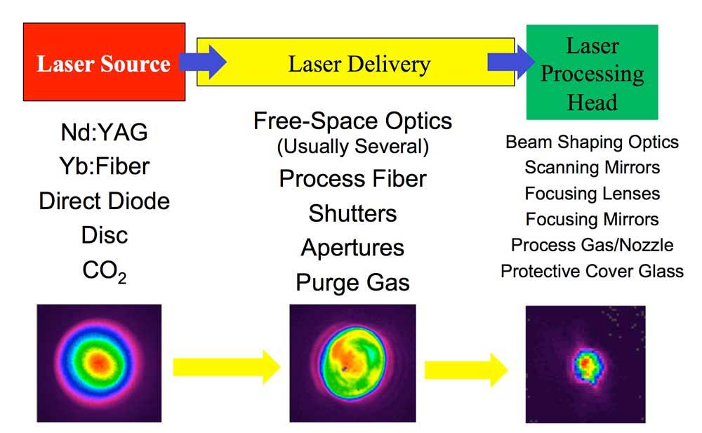
A good laser source doesn’t always translate into a good laser process. Consider Figure 6, where the beam power density distribution in the power source is clear, with a high concentration in the middle surrounded by outer rings of lower power densities. Once the beam travels through the delivery system, it must make its way through various components, depending on the laser system. These can include free-space optics (as in a CO2 laser) or a process fiber (as in a Yb:fiber laser), shutters, apertures, and purge gas.
The beam then goes through various components of the laser processing head, which (again, depending on the setup) can have beam-shaping optics, scanning mirrors, focusing lenses and mirrors, a protective cover glass, process gas, and a nozzle. Without good maintenance, all these elements can alter the power distribution and degrade the beam quality.
Good laser processes require good maintenance and benchmarking, as it is inevitable that the laser system will change over time. Ultimately, a laser process without adequate measurement is uncontrolled, and comprehensive measurement is a critical ingredient for controlling it.


The Fabricator is North America's leading magazine for the metal forming and fabricating industry. The magazine delivers the news, technical articles, and case histories that enable fabricators to do their jobs more efficiently. The Fabricator has served the industry since 1970.
start your free subscription
Easily access valuable industry resources now with full access to the digital edition of The Fabricator.

Easily access valuable industry resources now with full access to the digital edition of The Welder.

Easily access valuable industry resources now with full access to the digital edition of The Tube and Pipe Journal.

Easily access valuable industry resources now with full access to the digital edition of The Fabricator en Español.
Seth Feldman of Iowa-based Wertzbaugher Services joins The Fabricator Podcast to offer his take as a Gen Zer...


