


President
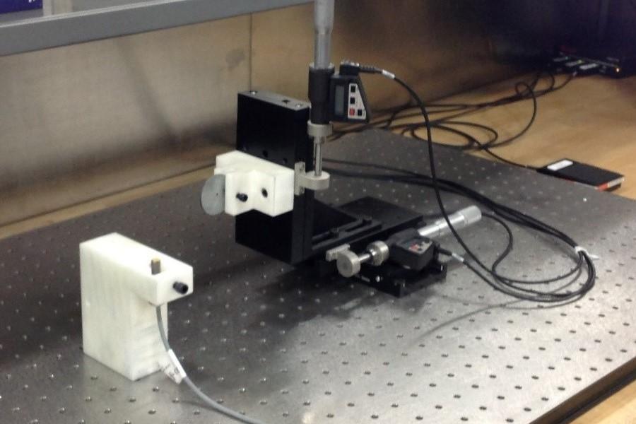
This is a test device that allows your tech to set up and identify the exact sensor field for a variety of sensors and materials. Micrometers move in all three axes and can plot the sensor’s range, sending the coordinates to a spreadsheet. Creating this map of the sensor’s effective range helps the operator select the proper sensor and design its installation concept before the tool has even been built. This saves time during the build and testing phases.
When in-die sensing was first implemented, it was primarily intended to halt expensive and disastrous die crashes. Once the technology had reduced die crashes to a rare event, it became apparent that in-die sensing could offer more opportunities for quality control—monitoring part quality to prevent the production of bad parts by stopping the process when a problem occurred, and in closed-loop systems to adjust tooling automatically on-the-fly to prevent the production of bad parts in the first place.
Preventing die crashes is the low-hanging fruit of an in-die sensing program. Once you have built a solid foundation of mistake-proofing to eliminate die crashes, you will have saved a boatload of money by preventing all the expenses associated with die crashes and tool repairs. You can build the rest of the in-die sensing program on this base.
With die crashes eliminated, you now are getting parts to your clients on time without “Mission Impossible”-style heroics in the toolroom and production floor. Your toolmakers are getting bored because they are not rushing to fix smashed tools like trauma doctors in the ER. They have time on their hands, and you want to take advantage of that.
The new goal is to detect flaws during the stamping process and stop the operation when a problem occurs. By using sensors installed in the tooling, you will be able to detect certain flaws in parts immediately, without waiting for someone to perform spot checks during production. This is particularly helpful if your shop is short on skilled, conscientious operators. Using in-die sensors, your process can become robust and stable regardless of the operator at the press, or even while it is running unattended.
If you are getting into this type of sensor work in the tooling, you’ll want to invest in two ways.
First, if you have not already done so, designate a dedicated sensor technician to eliminate crashes. This one person, typically a toolmaker, has the sole responsibility to apply sensors to the tooling. More often, you won’t be bringing in a new person; you’ll be selecting an experienced toolmaker from your group (who now has extra time because you fixed the die crash problem) who will move into this new position with new responsibilities.
Second, invest in a sensor lab. You’ll need to equip it with special tools and devices so the sensor technician can experiment and try out different sensors, test mechatronics, and test the sensors on the tooling in the toolroom.
One extremely popular and fairly simple way to check for visual defects and subsequent bad parts is with stripper level sensors. If you use spring strippers, the stripper plate surface should close at the same distance from the lower die plates every single stroke. Any object trapped between the strip and the stripper plate will prevent at least one corner of the stripper plate from traveling its full distance. Anything that changes that distance likely will cause a quality problem, even though it may not crash.
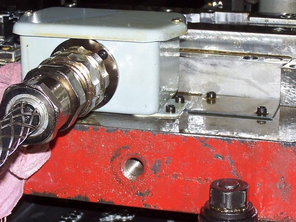
An “umbilical cord” connects all the sensors on the tooling to the press control. This way, all of the sensors can be connected at once, ensuring that they are installed correctly and allowing a quick connect/disconnect.
For instance, if a slug pulls back up with the punch and lands on the strip, the successive strokes will not typically cause a crash. However, the slug usually will dent the strip, resulting in visual defects in the parts being produced.
In addition, that trapped slug will cause the stripper plate to close unevenly. By checking the corners of the stripper with sensors that are set to detect the repeatable bottom position of the plate, you can detect—within one stroke—when the stripper plate does not close to its proper depth and stop the press.
In most applications, this can be done with inexpensive digital-output proximity sensors. Sensors are mounted on all four corners or diagonally opposite corners of the lower portion of the tool to monitor two or four corners of the stripper plate’s vertical travel. Typically, they are set so that the stripper plate must penetrate 1.5 times the strip’s thickness into all of the sensors’ sensing fields. Because a pulled slug is the same as the strip’s thickness, when it sits on top of the material, at least one corner of the stripper will not reach one of the sensors’ range. This causes a fault that stops the press.
On very thin materials, you will need to change to an analog-output proximity sensor. Using this type of sensor, you can measure stripper depth at the bottom with a tolerance of +/- 0.0005 in. When material is 0.010 in. thick or less, this is extremely common. Some analog sensors have been used in applications with material as thick as 0.040 in.
Many other things can get trapped between the stripper and the strip and cause the plate to close unevenly. This author has seen broken spring shards, punch tips, hand tools, steel rulers, and even shavings building up under the strip in a forming station, all detected by stripper level sensors that stopped the press and prevented the client from shipping bad parts to their customers.
For hole sensing, it is possible to check for the presence of the hole itself. This can be achieved with a springback probe that enters the hole when it is present without turning on a sensor. If the hole is not present, the punch stops traveling while the rest of the upper tool continues to close. A sensor in the upper tool then detects that the punch has not descended properly because of the hole’s absence. You may recognize this concept as being identical in practice to the old-school pin probe that has been used to monitor feed progression.
Another method for checking for a hole is to verify that the hole-making punch’s tip is still present every stroke. If a hole is missing, it is because the punch broke. Designers recognize as early as the design phase that a punch is likely to break if it is small relative to the material thickness. This is especially true if it is a very small punch. It may be easier to use an optical sensor to verify that the punch is intact than to devise a probe to enter a tiny hole.
Another way to perform in-die part quality control is to detect the presence or absence of a feature. This is especially helpful if you use tooling that incorporates some type of in-die assembly operation. This can be the insertion of a nut, assembling two different strips, or checking for a bowl-fed detail that must be inserted into the strip.
Digital sensors can check for the presence or absence of the feature being checked. Simple press controls can stop the press when they detect a problem. More sophisticated press controls can divert these parts on-the-fly to a scrap bin, stopping only if too many parts in succession are made incorrectly.
Force can be measured in the tooling itself as well. Tiny load cells can be built in to detect the force on specific punches when the punch’s sharpness affects part quality directly. This is rare and requires that the sensor technician take some special training.
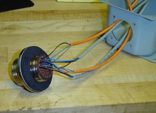
Adding sensors requires upgraded connections. This receptacle, which uses military spec connectors, has 54 wire connections available—enough to satisfy most applications.
Why force measurement? Imagine the scoring on a beer can top that enables opening it. That scoring into the material is done with a punch. If the score line is too deep, the can opens in the case. If it is too shallow, a thirsty person will not be able to pop it open to watch a kickoff!
Any significant change in force can indicate that a part has shallow or excessively deep score lines. Whether the change in force was caused by variation in the strip thickness or dulling and chipping of the punch, the force change can be detected and the process stopped before the bad part makes it downstream to assembly.
After stampers were able to master the practice of monitoring stamping operations to detect flaws in-die, they progressed to the highest level—detecting part variations and “automagically” adjusting forming stations to correct the process to make good parts. The sensors can help bring parts that have wandered out of the good-part range (or completely out of tolerance range) back into spec between strokes and without stopping the press.
This high level of in-die sensing uses a closed-loop approach to monitor and change the process automatically. It applies only under certain circumstances involving tight-tolerance, high-margin parts and typically high-volume production. Where it does have an ROI, it is invaluable.
Doing this requires the use of analog output sensors. Instead of providing just two states—on and off—analog output sensors produce a signal that is scaled relative to what the sensor is detecting. For instance, an analog sensor may detect the two extremes on a scale of one to 10: one if an object actually touches the sensor; 10 if an object is out of the sensor’s effective range.
Another example can be found on your car dashboard. The low-level fuel light is a digital-output sensor; on/off only. It does not tell you how much gas you have. It is off whether the fuel tank is full or ¼ full, and only turns on suddenly when it’s nearly empty.
The fuel gauge, however, is connected to an analog-output sensor. It puts out more voltage when the tank is full than when it is empty. The gauge’s needle is pinned to the right when the tank is full, at the halfway point when half the gas is gone, and all the way to the left when it is empty. The sensor sends a variable output, not on/off. The needle moves through its range, and its position is analogous to the current level of fuel in the tank.
So, a digital indicator says “yes” or “no.” An analog-output sensor tells “how much.” With a digital sensor, you can tell if something is there or not, or if a bend angle is good or bad. With an analog sensor, you can calibrate the sensor output and know the angle of the bend or the thickness of the metal.
Analog sensors are used the most on bend angles. They can measure these angles within fractions of a degree. If the angles change between strokes, servomotors spin to drive wedges in or out of the die, which changes an adjustable forming station to bring the part back into tolerance. This is closed-loop tooling. Sensors measure, and controls use the data to command servomotors on-the-fly. They do not just detect bad parts and stop the operation; they detect and adjust the tooling between strokes so you don’t make bad parts in the first place.
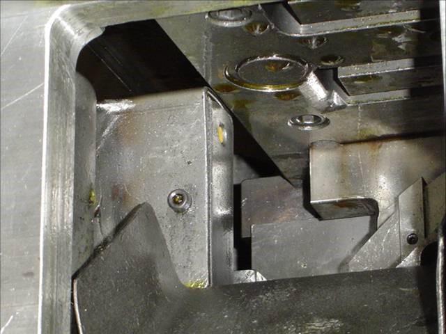
Barely visible is the yellow sensor face. It detects the depth of travel of the stripper closing. If the stripper fails to reach the sensor’s field, the control stops the press
It also is possible to measure material thickness and make changes. But how is this a self-adjusting process, and how can measuring material thickness affect the operation between strokes?
One way this capability can be used is in the stacked motor lamination market. If the tooling is stacking laminated sections together and entire completed stacks are being conveyed out from under the tool, material thickness matters. The sensor system can measure incoming material thickness and adjust the number of pieces in the stacks to ensure that the total stack height is within tolerance.
Another, more extreme example is a part that requires a precision coined thickness. Under certain circumstances, and with presses that have the capability, the shut height of the tooling can be changed on-the-fly so that the ram penetrates shallower or deeper to change the thickness in the coined area.
An in-die sensing program using these techniques allows a stamper to use a stable process that is monitored by press controls and sensors to complement the operator’s skills. It will yield savings by reducing crashes, halting operations when a bad part is made, and even correcting the process to prevent bad parts from being made in the first place—resulting in zero-defect parts shipments.
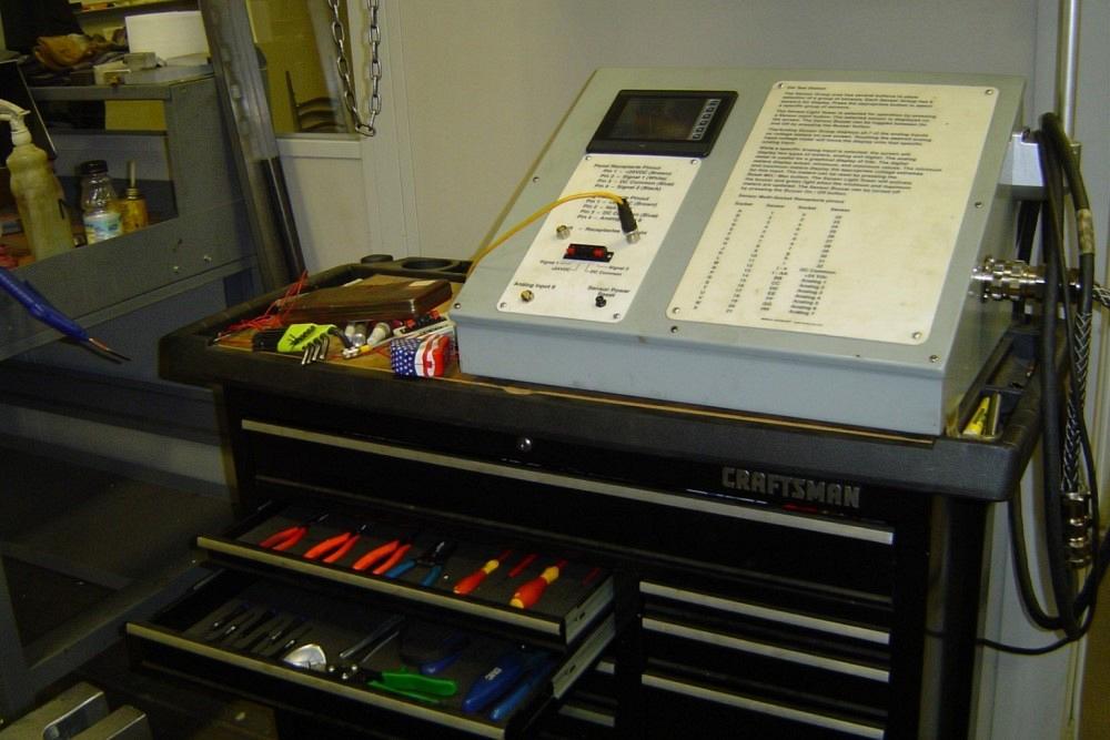
This rolling tool cabinet has a sensor tester on top that powers up sensors on the tools in the toolroom so final adjustments can be made without using valuable press time. The toolbox itself is full of special tools for working with and installing the sensors and the connection junction boxes.


The Fabricator is North America's leading magazine for the metal forming and fabricating industry. The magazine delivers the news, technical articles, and case histories that enable fabricators to do their jobs more efficiently. The Fabricator has served the industry since 1970.
start your free subscription
Easily access valuable industry resources now with full access to the digital edition of The Fabricator.

Easily access valuable industry resources now with full access to the digital edition of The Welder.

Easily access valuable industry resources now with full access to the digital edition of The Tube and Pipe Journal.

Easily access valuable industry resources now with full access to the digital edition of The Fabricator en Español.
Seth Feldman of Iowa-based Wertzbaugher Services joins The Fabricator Podcast to offer his take as a Gen Zer...


