Contributing Writer
An in-depth examination of electric resistance welding (ERW) weld nuggets as a quality control step in the manufacturing of high-strength tube and pipe used for pressure applications has been a proprietary procedure for some manufacturers for several years.
Types of pressure-application tube and pipe are cross-country line pipe, such as API 5L grades for the transmission of oil and gas; down-hole casing for oil and gas wells; and pipe used in oil and gas refineries.
This article focuses on the fundamental steps required for any manufacturer to develop such a procedure.
Regardless of the frequency of the power source used to make longitudinal butt welds in tube and pipe, a discernable hourglass shape signature is present when the ERW process is used.
This hourglass shape signature, or pattern, is the result of electrical current flow in and around the edges of the in-process material. The depth of the heat into the edges is controlled by the power source frequency (seeFigure 1).
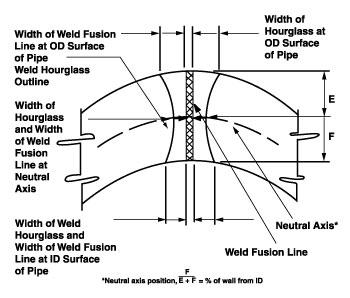
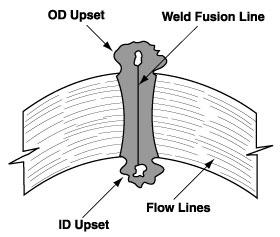 |
| Figure 1: This typical hourglass signature of an ERW weld nugget macro shows the upsets still intact. The most useful weld nugget sample is taken in a transverse plane through the weld seam. |
The ERW tube and pipe industry usually separates the power sources available into the low-frequency range (rotary electrodes) and the high-frequency range (induction coil or sliding contacts).
Heat penetration into the edges of in-process material--usually hot-rolled steel--may be as deep as 0.375 inch when welded with a low-frequency power source. The use of low-frequency welding machines to produce pressure tube and pipe no longer is acceptable for most specifications and customer requirements.
Compared to a low-frequency power source, heat penetration produced by a high-frequency power source into the edges of in-process material will be greater at the top and bottom corners and less at middle wall. The lower the output frequency (60 to 1,000 cycle), the deeper the heat penetration.
Higher frequencies (450,000 cycle/ second, or 450 megahertz) result in less penetration. Average heat penetration for a 450-megahertz power source is approximately 0.030 inch into each edge.
Heating tube and pipe edges with a high-frequency power source provides a number of surface conditioning operations to help achieve an acceptable ERW weld joint. Surface conditioning occurs when the edges are brought together and the compressive force of the welding rolls is applied to achieve deformation.
Metal extrusion can occur on the inside and outside surfaces of the welded material. This extrusion forms a typical ERW weld. Upsets occur because of the excessive force on the welding rolls, which is necessary.
Some national and international specifications require reheating of the tube or pipe's ERW longitudinal weld to a temperature necessary to eliminate the untempered martensite structure formed because of rapid cooling of the narrow heat-affected zone (HAZ). This reheating is referred to as a normalizing operation.
Untempered martensite is a hard element formed when a heated weld nugget passes through the cooling cycle too quickly. If it is not reheated and allowed to cool slowly, it will remain, reducing the ductility of the weld area. If untempered martensite remains in the weld area, it causes corrosion because of stress in the area.
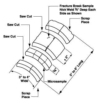 |
| Figure 2 The fracture break sample reveals the longitudinal structure of the weld area. |
Some of the weld samples are unwelded; some are welded but have extrusions or upsets that are not removed or normalized; some are normalized and have upsets removed; and some are single-edge samples at various locations along the mill line (see Figure 3).
Accurate, sharp delineation of the microstructure of the ERW weld sample in various conditions along the process line is important to characterize the size, shape, composition, and fault (if any) of the weld. The optics required to examine an ERW weld macro are not a major capital investment compared to the optics required to examine an ERW weld micro.
These samples normally are examined metallographically either in the micro or macro condition. Micro samples differ from macro samples in the amount of time needed for examination, the number of finishing steps (grinding and polishing) performed, and the complexity of the examination.Usually, a sample is prepared in the macro condition, acid-etched, and examined first under a microscope at approximately 50 power magnification. Preparing and evaluating the sample takes five to 10 minutes.
 |
| Figure 3 This normal ERW tube and pipe weld geometry has the weld bead upset removed. |
If additional examination is required or requested, such as in the micro condition, the sample should be mounted and finished.
Finishing a sample to the micro condition takes about an hour. The author is not familiar with any commercially available device that attaches to the microscope to aid in the measurement of flow line angles. There is, however, a generic design available that works well with several microscopes. Also, a layout and listing of recommended equipment for a weld lab station is available.
A tube and pipe manufacturer that is required to produce a product to a specification or customer requirement, for example, with a specific grain size and grain count, and no untempered martensite, must be equipped to perform the appropriate sampling procedures.
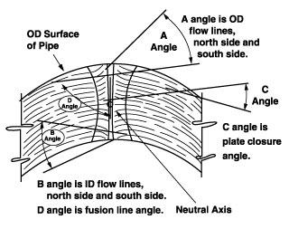
The plate closure angle on the microscope is greater for small-diameter tube and pipe than for large-diameter pipe. When the fibers of the in-process material are joined to form the ERW weld nugget, they are not parallel, so they form an angle with each other from side to side. The fibers form the plate closure angle from each side of the material at the neutral-axis position.
 |
| Figure 4 Different flow lines are visible after proper preparation and etching. |
Some ERW tube and pipe producers have SOPs for determining variation in the width of the white bond line recorded for different production runs of the same product.
In the examination of an etched ERW weld nugget, one criteria for determining if the two opposite edges are fused (welded) is if the white bond line, which should be uniform in width and without voids or interruptions, extends from the outside surface of the tube or pipe to the inside surface.
When the ERW weld nugget is examined with the upsets intact, the white bond line should extend into the upsets, top and bottom. A vertical white bond line that is wavy indicates material movement in the weld zone. Some of the causes of this movement may be camber in the material, twisting, buckling, or waving edges out of the finned stands.
Any ERW tube or pipe producer that uses a microscope to examine welds and related samples for mill control can record and coordinate mill data and weld sample data with statistical process control charts.
It is important in tube and pipe producing to prevent introduction of the twin V in the welding zone (seeFigure 4). This is accomplished by controlling the height of the unwelded can as it exits the last finned stand. In the real world, however, this cannot always be done.
When edge enhancement equipment is not used in the mill line to improve the cut edge condition after the in-process material has entered the mill, then the cut edge must be smooth and solid when the material is delivered to the mill to achieve an acceptable fusion of the two edges.
Examining the cut edge of the in-process material from the slitter operation or the mill line edge trimmer in the macro sample shows the operator the condition of the cut edges entering the mill line.
When hot metal is rolled, forged, or cold-worked, a directional flow pattern is developed to change its original shape. This flow pattern consists of streaks and striations. The orientation of this pattern, with respect to the new surface, indicates the direction of metal flow during deformation.
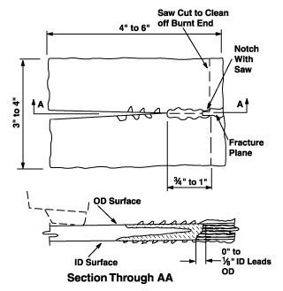 |
| Figure 5 A welder stop sample shows the twin V with its position on the outside and inside surfaces and how to determine and measure the difference between the two. |
Flow lines are made visible during macro sampling because the elongation of inclusions and other elements are selectively attacked by the acid etching reagent. The effect of the flow lines generated by the action or force of the rotary shearing blades can be very confusing to examiners of a weld macro. If edge enhancement is installed in the mill line and it is properly used by the operators, these flow lines can be removed (see Figure 5).
Examining the different elements of ERW weld nuggets and recording these elements on a control chart will not result in immediate quality improvement. A database must be developed over time that records all elements for all diameters, wall thicknesses, and grades of product produced at a mill.
The results of different production runs must be compared with the recorded elements to determine the upper control limits and the lower control limits of each element. Then, decisions can be made regarding necessary adjustments to the mill settings and possible roll contour design changes to change the elements and improve the quality of the product.


The Welder, formerly known as Practical Welding Today, is a showcase of the real people who make the products we use and work with every day. This magazine has served the welding community in North America well for more than 20 years.
start your free subscription
Easily access valuable industry resources now with full access to the digital edition of The Fabricator.

Easily access valuable industry resources now with full access to the digital edition of The Welder.

Easily access valuable industry resources now with full access to the digital edition of The Tube and Pipe Journal.

Easily access valuable industry resources now with full access to the digital edition of The Fabricator en Español.
Seth Feldman of Iowa-based Wertzbaugher Services joins The Fabricator Podcast to offer his take as a Gen Zer...