


Contributing Writer
Edge treatment of coil strip before it enters a tube and pipe mill, called skiving, is a rapidly advancing technology. Improving the coil edge before it is welded helps increase the quality of the seam join and helps prevent rejected tube or pipe.
Edge skiving to obtain smooth abutting edges for seam welding has been a viable process for many years. Most traditional skivers use triangular high-speed steel cutting knives held in bolted, clamped holders.
The toolholders are rigidly mounted on movable screwjack slides and are manually engaged with the strip to attain the desired depth of cut. Each tool is manually set, with the individual screwjack settings determining the depth of cut with each tool and, therefore, the tool load sharing.
Traditional skiving units are most successful at speeds above effective planing speeds, or about 40 feet per minute (FPM). Below this speed, the metal tends to tear instead of being smoothly cut, resulting in jagged edges that can be worse than the "as slit" edge.
Cambered material can jam between the rigid tools used with this equipment, causing tool blunting and changed depth of cut.
When tools wear and become blunt, they have a tendency to chatter, which can cause a rough finish and poor welds. In addition, blunt tools cannot easily be changed on-stream. They must be retracted by hand and another tool station advanced to replace the cutting action of the defective tool.
The load sharing and depth of cut of each tool depends on the individual tool settings. Uneven tool wear upsets the selected load sharing.Traditional skiving equipment has been generally satisfactory, but modern mills are now demanding higher quality, a wider operating range, and less operator dependency.
For instance, since most tungsten inert gas (TIG) welding mills using stainless steel, high-alloy steels, titanium, or aluminum must run slower than 40 FPM, these materials must be used "as slit."
Untreated or imperfectly treated edges cause pinholes in completed welds. The product is often 100 percent inspected for defective welds using ultrasound, and defective lengths are scrapped. As much as 2 percent can be routinely rejected in some mills.
Conventional edging equipment performs well with high-speed mills when properly set up with sharp tools and when the material is of uniform width and free of camber.
 |
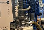
| Figure 1: A nonvibratory modular skiving unit with an integral air actuator is suitable for high-speed, heavy skiving. |
Recent research and development has resulted in a range of new skiving equipment being developed.
A four-station edger suited to skiving at down to near-zero strip speed is available to the market. This patented edger uses electrically vibrated tools that impart relative movement between the tools and strip at all times. The vibration amplitude is fully adjustable, and so is the cutting pressure and depth of cut on each module.
These machines have a skiving speed range of 0 to 600 FPM. Each mini tool carriage is oscillated in the direction of material travel. The frequency can be varied. The higher the frequency, the less the depth of cut and the better the finish. Because vibratory action is in the direction of material travel, vibration perpendicular to direction of travel (or chatter) is suppressed.
Figure 1shows a nonvibratory modular skiving unit with an integral air actuator. This unit is suitable for high-speed, heavy skiving. It is incapable of tool chatter, using an entirely different principle than does vibratory tooling.
 |
| Figure 2: Modular units can be mounted in adjustable-angle protractor frames for cutting any selected angle on the material edge. |
The tool module shown in Figure 1 is bolted in an adjustable-cutting-angle protractor frame. Any chatter that tries to develop in the tool is immediately damped by the roll. The patented cutting head has no natural vibration frequency and therefore cannot chatter.
Figure 2shows these modular units mounted in adjustable-angle protractor frames for cutting any selected angle on the material edge. Note that the idler roll is omitted in this case. In tube and pipe mills, only the upper quadrant is used. For variable-width materials, these protractor frames are installed on movable carriages (see Figure 3).
The floating tool heads on the modular units share cutting loads when fed with the same actuating air pressure. To increase the depth of cut uniformly on all tools, the pressure is increased from the central controller.
Figure 4shows an indexing head that engages each of the four edges of the carbide insert on command. Each cycle of the remotely operated air operator lifts the tool off its mounting and rotates it 90 degrees, presenting the new edge.
As shown in Figure 1, the sliding air actuator/linear bearing module allows the rocker carriage to float on the edge of the material. If camber is present in the material, the cutting heads follow the edge as it changes angle and moves side to side between the limits of the actuator stroke, allowing a constant depth of cut to be maintained without jamming, tool wear, or tool breakage.
Several other developments have addressed additional skiving problems.
Swarf needs removal or special treatment if copiously generated, because it can jam between the tool and the material. Reciprocating swarf extractors are available that pull balls of swarf away from the cutting vicinity.
 |
| Figure 3: Protractor frames can be assembled onto a moving carriage for automatic edge tracking. Note the gears on the carriage base for keeping the carriage aligned as it moves. |
Automatic edge tracking uses air-motor-driven carriages fitted with sensors and a closed-loop control system to lock onto the edges and continuously follow them. This feature is helpful if the material varies in width during the run, if the material can move from side to side, or if carriage guides must retract clear of coil joins and then automatically re-engage the material after the join is passed.
Tool mounting systems that use controlled force instead of controlled position can attain stable cutting even under shifting conditions. Also, the absence of massive, fixed-position mounting hardware enables the use of lightweight tool support structures capable of edge following, variable angle cutting, and variable rake angle operation.
Vibratory tooling allows accurate cutting of very thin materials. The vibratory motion peels off very thin layers of cut material. With this tooling, the minimum depth of smooth cutting is about 0.001 inch.
 |
| Figure 4: An indexing head engages each of the four edges of the carbide insert on command. |
The skiving process is still in need of improvement. Higher-frequency oscillation of vibratory tools is being developed to give better finishes at low cutting speeds. Also, new methods of reducing the effects of tool wear are being developed.
Edge sensing rolls fitted with sonic detectors are being designed to enable edge quality monitoring on-stream. These can be used to initiate automatic tool changing. The process is slowly evolving into self-checking smart technology.
New edge treatment technology enables effective on-stream edge processing of any common metallic material processed in a tube or pipe mill. Although many challenges remain to be addressed by future developments, currently available skiving equipment offers flexibility and minimum operator dependency.

The Tube and Pipe Journal became the first magazine dedicated to serving the metal tube and pipe industry in 1990. Today, it remains the only North American publication devoted to this industry, and it has become the most trusted source of information for tube and pipe professionals.
start your free subscription
Easily access valuable industry resources now with full access to the digital edition of The Fabricator.

Easily access valuable industry resources now with full access to the digital edition of The Welder.

Easily access valuable industry resources now with full access to the digital edition of The Tube and Pipe Journal.

Easily access valuable industry resources now with full access to the digital edition of The Fabricator en Español.
Cameron Adams of Laser Precision, a contract metal fabricator in the Chicago area, joins the podcast to talk...