


Assistant Professor
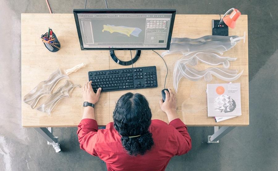
It’s important to understand that there’s a big difference between DFAM and traditional design for manufacturing/design for assembly. Image: Autodesk
A lot of excitement surrounds additive manufacturing (AM) right now, and every day new stories come out about the benefits of the technology.
Manufacturers that haven’t acquired a 3D printer sometimes feel like they’re missing out. Or they’re unsure how to get started with AM—or if they should even get into 3D printing at all.During my 11 years of teaching mechanical engineering at the university level, I’ve advised dozens of manufacturers contemplating the adoption of 3D printing. If you’re thinking about it, before jumping in you should:
Before Buying a Printer
Many people have told me they want to 3D-print their (fill in the blank). I ask if they have worked with 3D printers before. The answer often is “no,” but they have seen how easy it is to print parts. Then they start asking me which printer I would recommend.
This is where I usually tell them that AM is not that simple. Before talking about printers, it is important to know what material you will be printing. The decision between choosing a plastic or metal printer is significant, particularly in terms of cost. If the goal is to simply prototype parts, then choose a plastic printer. They cost as little as $500. High-end models ($100,000) can be used for production applications, as well as prototyping.
Metal printers start at around $100,000 and can cost as much as several million dollars. They typically are used just for serial production.
Another important consideration is the postprocessing equipment needed to finish 3D-printed parts. Postprocessing operations range from solution baths for high-end fused deposition modeling (FDM) machines—to remove support structures—to grinding wheels that impart the final finish to metal 3D-printed parts.
Thought also must be given to material costs, which depend on the type of machine used.
With plastic printers, the FDM build material is filament, stereolithography (SLA) uses liquid resin, and selective laser sintering (SLS) requires powder. Filament is generally the least expensive, costing $20 to $70 per kilogram, compared to an average cost of $50 per liter for SLA resin and $45 to $75 per kg for SLS powder.
For metal there’s either wire for directed energy deposition (DED) or powder for DED and powder bed fusion (PBF). Wire tends to be less expensive than powder, averaging approximately $2 to $25 per kg. DED powder runs around $50 per kg, and PBF powders range from $350 to $550 per kg.
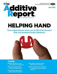
Different AM technologies require different types of DFAM optimization. If the part at left were built with FDM or SLA technology, significant material and time savings could be realized if the bottom angle of the cuff feature were changed 5 or 10 degrees. This is an issue with PBF because the powder acts as the support, so there’s no need to print support structures.
With all the available styles of printers, ancillary equipment,
and materials, it may be hard devising a printing strategy. This is when you must consider the main design features of your part, the number of parts the printer must build, and the capabilities within your company to make the project succeed.
Design Considerations
It’s important to understand that there’s a big difference between design for additive manufacturing (DFAM) and traditional design for manufacturing/design for assembly (DFM/DFA). When using DFM software for injection molding applications, for example, the designer uses draft angles that facilitate part ejection.
With DFAM software, on the other hand, negative draft angles can be designed and, if done right, there’s no need to design mating surfaces. When designing a casting it’s necessary to think about subassemblies, such as gates and riser cores, and design around those features. This increases the complexity of the design because, as with the molding example, features are being added to help facilitate the manufacturing process. With DFAM no tooling or additional features are required to 3D-print, so you can start designing your part as you need it to be. Other differences to be aware of with DFAM relate to designing with polymers versus metals and using different styles of 3D printers.
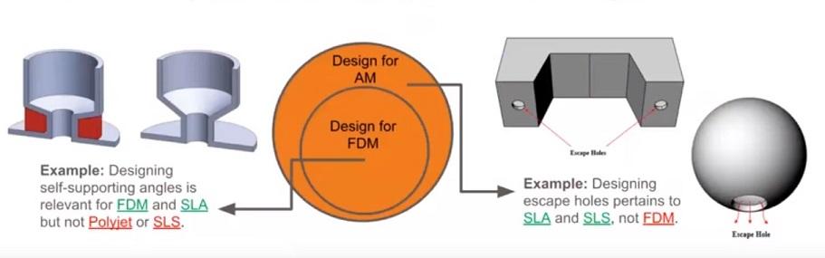
The AM system and software supplier Fisher Unitech has posted a good blog to its website titled “7 DFAM Principles.” The author writes that different AM technologies require different types of DFAM optimization. The image above illustrates this idea.If the part at left were built with FDM or SLA technology, significant material and time savings could be realized if the bottom angle of the cuff feature were changed 5 or 10 degrees.
This is an issue with PBF because the powder acts as the support, so there’s no need to print support structures.The part at right shows the importance of designing escape holes when printing with SLA or SLS technologies. Doing so reduces waste material by preventing material from getting entrapped in the part. If you were to print this part with FDM, there would be no benefit to printing escape holes.
A major consideration when dealing with DFAM for metals is regulating thermal conditions to minimize warpage caused by residual stresses. These stresses build up in the part during manufacturing because of the high local energies applied by the laser or electron beam. As such, DFAM for metal necessitates controlling geometries to minimize heat in a given region. One way to lower heat would be to avoid designing thick sections because they promote heat buildup.
Lowering Part Count
The objective of DFA is to simplify the assembly process. 3D printing helps manufacturers do this rather easily. I recall reading a blog about AM that described a 3D-printed rocket-fuel injector designed by NASA that consisted of two parts. If manufactured conventionally, it would have had more than 200 components.
Currently some of my students at Northern Illinois University (NIU) and I are working with RadMax Technologies Inc. , a Spokane, Wash., compressor manufacturer that wants to lower the part counts of prototypes for a refrigerant gas expander.
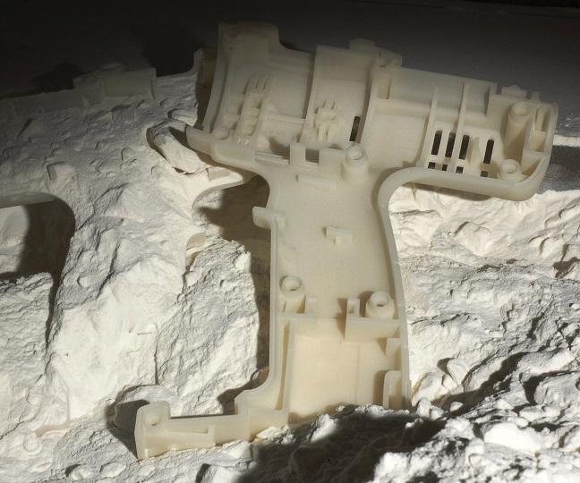
Before investing in 3D printing, prospective users need to consider postprocessing of parts.
The expander’s design permits two complete intake-and-discharge expansion cycles on each cam in the standard two-cam configuration. The design allows each cam to be configured with a different expansion ratio. Different porting options into and between the sections permit stable expander speed control, because of changing gas flow conditions, and the possibility of multistage expansion in one device.
RadMax has produced numerous prototypes thus far; each incorporates more than 20 conventionally machined parts. The company wants to see if metal 3D printing would yield prototypes having just a few parts. RadMax and the NIU team have made good progress thus far, and we’ve learned the importance of simple things, like project partners using similar CAD versions to prevent errors when converting a CAD file for printing.
“Discomfort” Zone
To guarantee the successful use of additive at your company, it is critical to develop a streamlined, closed-loop communication channel that extends from management through every level of your operation and back to management. Adopting AM also will require you and your team to commit to using it long enough to accurately assess it. This could necessitate operating outside of your manufacturing comfort zone.
Not everyone is willing to do this or devote the time necessary to optimize an AM process. That was the case with a client of mine that supplied products to the automotive industry. The client wanted to 3D-print some fixtures for mounting parts during assembly. I indicated it would be my team’s first time printing such a fixture and extra development time would be needed. We would be depositing a lot of metal and had to find a way to control thermal distortion. That took longer than we hoped, and, in fairness, our solution wasn’t perfect.
The fixture’s heaviness was the client’s main concern, and the company decided to pull the plug on the project before we could demonstrate ways to reduce the weight. I do not think the project was a failure, and our team learned a lot. But it was clear the client wanted quick answers and was unwilling to go the distance with us to find them.
Manufacturing processes—especially those involving new technologies like 3D printing—can’t be implemented as quickly as everyone would like. It is important to always communicate that upfront and ensure that all team members and partners understand it.
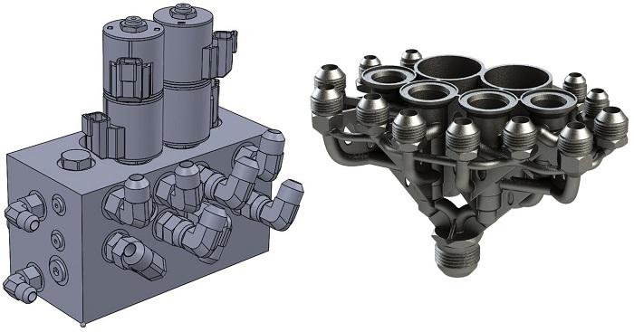
The hydraulic manifold at left was designed to have 13 machined parts. The 3D-printed version at right is a one-part structure that weighs 91 percent less than the machined version. Image: Atlas Copco.
In this episode of The Fabricator Podcast, Caleb Chamberlain, co-founder and CEO of OSH Cut, discusses his company’s...
