


Application Engineer
Even though GMAW is a relatively simple process to execute, the moving parts that make up the process determine the success of the welder and the quality of the finished weld.
Though the basic principles of gas metal arc welding (GMAW) haven’t changed in 70 years, the equipment, the alloys, and the technology producing the arc have all progressed and continue to do so. While these advancements have simplified things, especially for new welders, there is still much he or she must be aware of to perform GMAW successfully.
A good weld has many moving parts, so the more you know about the base metal, consumables, weld parameters, torch angle, and travel speed, the better chance you’ll have of producing a quality weld on a consistent basis.
The best place for new welders to start is with the base metal. The type of material, thickness, and whether the metal is coated are all important factors. These properties will affect the weld, including machine setup, filler metal type, shielding gas, and even which welding process to use. Essentially, everything begins with the base material. A fillet weld on mild steel is one of the most common applications that you might encounter. This basic weld will be the example used in this article.
Be sure to prep your base material properly. New welders sometimes overlook this step because it can be time-consuming, but it’s critical to getting the best possible weld.
The basic machine setup for GMAW requires a constant-voltage power supply set on direct-current electrode positive (DCEP). Some of the newer GMAW power sources are set this way by default, but if your machine isn’t, be sure to adjust it to the appropriate settings.
Once you’ve inspected the application, it’s time to select a filler metal. Choosing the incorrect wire may compromise the strength of your weld, but how do you know which works best? This choice depends on matching the wire composition to the base metal, knowing how clean the metal is, and the type of shielding gas to be used.
The wire diameter you choose depends on the thickness of the base material. Going back to the fillet weld example using 14-gauge mild steel, a likely choice is ER70S-6 in a diameter range of 0.035 to 0.045. The ER70S-6 (also referred to as S6) contains more silicon than ER70S-3 (S3). This makes it more forgiving of impurities like rust and dirt. However, this wire may form more silicon islands after the weld as the silicon brings those impurities to the surface. If your base metal is clean, the S3 might be a better wire choice.
Another consideration for wire is ensuring the cast and helix of your wire are appropriate. Not sure what that means? Well, if you take a length of wire, maybe 2 ft. long, and toss it on the floor, the cast is the diameter of the circle the wire forms. The helix is the arc of a single strand of wire when lying flat, or how far it rises off a flat surface. Be sure to check that your wire has a minimum cast of 15 in. and less than 1 in. of helix to ensure proper feeding. Otherwise, the wire may not make consistent contact inside your torch, which can cause premature contact tip wear or even loss of arc and decreased productivity.
Depending on your application, certain gas mixtures are more suitable than others. A universally good mix for welding mild and carbon steels is 90 percent argon/10 percent CO2. This is the mix of choice for the fillet weld example. If you are welding thin-gauge material at low power, a 75 percent argon/25 percent CO2 mix is more cost-effective yet still allows for proper adhesion without burn-through. If you are welding aluminum, a pure argon shielding gas works best. As always, know your application and your choices.
Before you set torch to metal, you need to set other welding parameters, like wire feed speed and voltage. These settings are key to manually fine-tuning your weld. In older machines, for example, you might have one knob for wire feed speed (or power) and one for voltage. Many of the new power sources have built-in programs or synergic lines that adjust these variables based on the way the arc behaves. The word synergic describes the link between the wire feed speed and voltage. These machines let you use a single knob or even a touchscreen interface to adjust the voltage in relation to the wire feed speed.
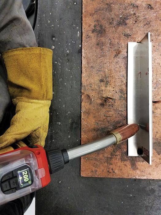
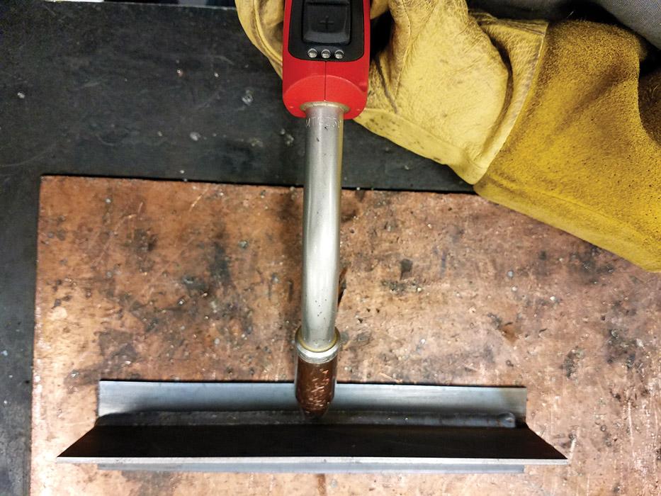
Figure 1
The push method preheats the metal, pushes the weld pool in the direction that you are traveling, and allows you to see where you are going.
Synergic systems allow you to adjust parameters quickly. You need to preselect the welding process, wire type, wire diameter, and shielding gas before you adjust the parameters. After preselection is complete, the wire feed speed is adjusted automatically to the application, often during welding.
With the wire feed speed set, you can make adjustments to the voltage using the arc length correction or trim. A short arc length generally yields a faster travel speed but has the possibility of generating more spatter. A long arc length often requires a slower travel speed, and though spatter is minimal, you may experience problems with undercut. In most cases, setting the parameters requires trial and error, but this time can be minimized with the synergic functionality of newer equipment.
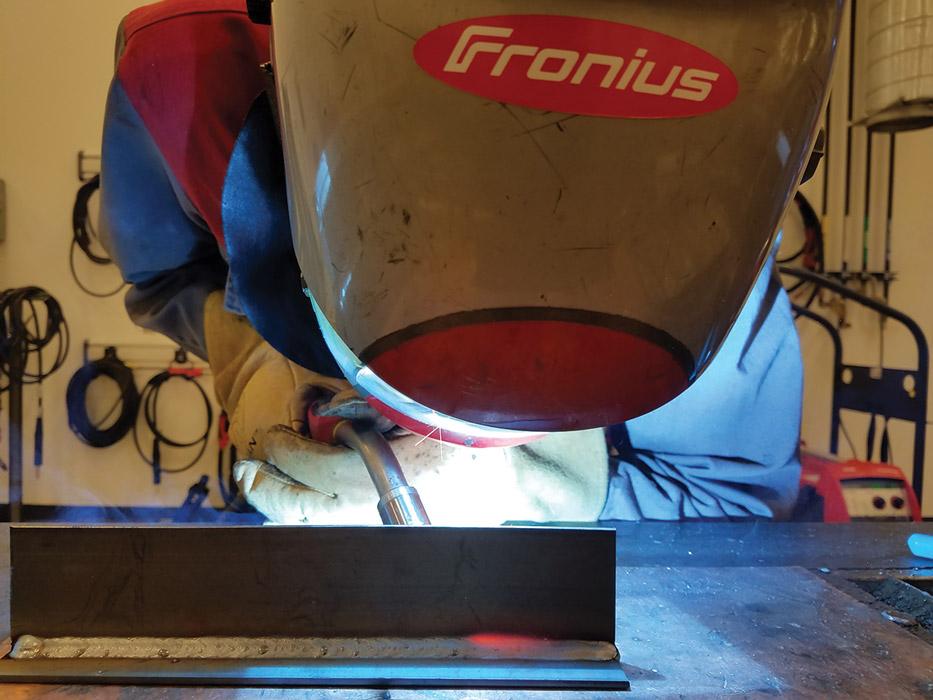
With all of the parameters set, the next decision involves torch angle. The push, or forehand, method preheats the metal and pushes the fluid weld pool along in the direction of travel (see Figure 1). This method provides a low-profile bead and enables you to see where you’re going.
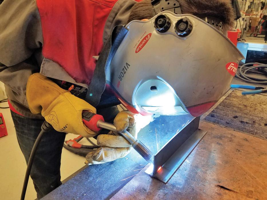
A pull motion refers to when the torch is angled back at the weld puddle and is dragged away from deposition (see Figure 2). This can provide a taller or deeper bead and puts the focus on where the weld has been. Neutral means your gun is completely perpendicular to the seam (see Figure 3).
Going back to our mild steel example, either torch angle will work. Use whatever provides the best weld for the application. If you are welding aluminum, be certain to always use a push method. Otherwise, you risk causing a significant amount of porosity and sometimes burn-through in your weld because of the decline in shielding gas coverage that can occur with the pull method.
Travel speed is key to successful welding and can be tricky to master. Keep in mind that your amperage settings determine your travel speed. If you are welding at a high amperage, you’ll need to increase your travel speed to avoid burning through the base metal. Low-amperage welding reduces the heat input to the base material to minimize distortion, but it can cause weld defects like lack of fusion. Be sure to move slower to keep the weld puddle fluid to avoid those fusion issues. There is no setting to compensate for your travel speed, even on the most advanced machines, so be sure to maintain a constant contact-tip-to-work distance, and watch the weld puddle solidify to ensure it is uniform from start to finish.
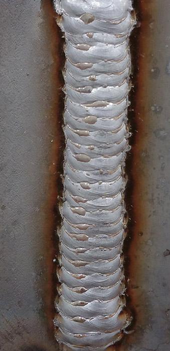
You’ve got a couple of choices when it comes to bead appearance. To achieve a bead that resembles stacked dimes, use a whipping motion or a process that changes the wire feed speed automatically. To achieve a nice weave bead, make sure the toes of the weld are uniform in both size and shape (see Figure 4). One of the disadvantages of weaving is a higher heat input, but if a larger weld bead is needed, a weave provides a visually pleasing option.
Once you’ve finished welding, take a look at the bead as well as the surrounding areas. Is there porosity, undercut, cracking, or lack of uniformity? If so, it’s time to work back through the choices you’ve made in an attempt to fix what went wrong.
For example, let’s say you see a bit of undercut. That means the base material is eroded and the weld pool didn’t fill the eroded space. This can happen if the voltage is set too high, the travel speed is too fast, or the wire feed speed is too slow. Undercut in a weld causes an area of weakness where the base material is thinner than the rest of the piece. The area with the thinnest cross section (the undercut) is the weakest point and where the weld will likely fail, either immediately or over time. On the next weld, be mindful of travel speed and voltage to avoid further defects.
If you use the appropriate materials, machine settings, and techniques, your weld should be free of visual defects like cracking and porosity and have a uniform shape and size. However, don’t rely solely on these visual cues. Testing will be able to show you whether your parameter choices, your techniques, and your skill yielded an acceptable weld and provide you with the confidence that you are headed in the right direction. Keep in mind that you can work through each new welding application by understanding what needs to be accomplished and the options available to you.


The Welder, formerly known as Practical Welding Today, is a showcase of the real people who make the products we use and work with every day. This magazine has served the welding community in North America well for more than 20 years.
start your free subscription
Easily access valuable industry resources now with full access to the digital edition of The Fabricator.

Easily access valuable industry resources now with full access to the digital edition of The Welder.

Easily access valuable industry resources now with full access to the digital edition of The Tube and Pipe Journal.

Easily access valuable industry resources now with full access to the digital edition of The Fabricator en Español.
In this episode of The Fabricator Podcast, Caleb Chamberlain, co-founder and CEO of OSH Cut, discusses his company’s...


