


Senior Editor
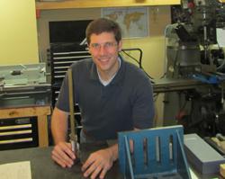
Late last year Owsley “Oz” Cheek launched Proto Machine Works, a fixture design and manufacturing company in Huntsville, Ala.
When politicians and pundits talk about America’s dire need for a technically capable workforce, they’d be happy to hear about Owsley “Oz” Cheek. After high school Cheek went to work at GH Metal Solutions in Fort Payne, Ala., in 2005. As a production machinist, he learned the manufacturing ropes, including CNC programming. While working at GH, he went back to school to get his engineering degree, and he joined GH Metal’s tool and die team.
Now the young engineer has launched his own fixture design house, Proto Machine Works. The Huntsville, Ala.-based company manufactures custom fixtures and designs standard fixture components. CAD-savvy and ever questioning the status quo, Cheek was instrumental in helping GH Metal adopt a robust fixturing strategy for its robotic welding cells—no easy task for a high-mix, low-volume manufacturer.
So many talk of the cost behind designing robotic welding fixtures, but for the past several years Cheek has effectively helped design such fixtures and quick-change mechanisms that take cost out of the overall manufacturing process, mainly by making manufacturing steps simpler and streamlining part flow.
Dissimilar parts may have common attributes that call for similar fixturing strategies. And even in low- and medium-volume environments, seemingly complex fixtures can make economic sense, Cheek said. It just takes some unconventional thinking, including ways to keep design and build cost out of the fixture.
The FABRICATOR: What’s the goal of a fixture design for a welding robot?
Cheek: We need to make the weld fixture as simple as possible. That’s the goal of any tool design, really. You don’t want to overcomplicate it. I see a lot of different ideas as to what needs to come first in fixture design, and I have my own ideas about that.
Many say that design for manufacturability plays into the process, and it does. But from my experience, making even small design changes when working with large customers can take a lot of time, and time is money. If the customer is open to design changes and approves them quickly, then by all means discuss those changes. If not, your time may be better spent coming up with a fixture solution for the existing part.
If you’re using 3-D software to design the fixture, the first thing to consider is the orientation of the part, or multiple orientations, if you need more than one step. And with robotic welding, in most cases you’ll need more than one step. The operator may have to reorient the part. If you can make the fixture design simpler, you do not need to get the entire weld finished in one step.
It’s true that the more times you reposition the part, the more chances there are for error. But to reduce that error, you can try to hold the part off of the same faces for each step, so you use the same datum points. It’s a balancing act. Yes, you’ll spend a little more money on fixture materials, and you gain some downtime as the operator reorients the part. But by creating more welding steps, you make each step simpler.
The FABRICATOR: Are there ways to streamline fixture build time?
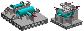
Cheek designed these welding fixtures using laser-cut components, which reduced fixture cost by 50 percent.
Cheek: New technology helps reduce that time, and the most obvious is designing fixtures in 3-D CAD software. Some now also are using coordinate measuring arms to speed the process.
With any weld fixture, you build in adjustability. When you’re finished with your fixture and need to make adjustments, there are a few ways to do it. You put the part in it, then simply push the stops to all the components and tack them down. Of course, this requires that you have all the components.
In a lot of job shops really on their game, everything happens in virtual space. Components are getting made at the same time the fixture is getting made. Many times the fixture is ready before all the components are ready. If you don’t have the parts, what do you do?
Today some coordinate measuring arms have software that shows you the 3-D model on the screen. Using the arm, you simply locate each of your adjustable points to where they’re supposed to be, and lock them down. You’ve done it without the parts and you’ve probably done it more accurately, because you’re connected to the model. Real parts have variability to them.
The FABRICATOR: How does machining and build time factor into the cost equation?
Cheek: Before considering machining, step back a little. Must all custom fixture components be machined? What about laser-cut parts?
Using laser-cut parts does make for a more complicated design process. It’s a little like working with a 3-D puzzle. But if you can integrate 3-D CAD automation with the design of the fixture using laser-cut parts, you can cut your fixture costs in half.
This especially applies to larger fixtures that use a lot of material, which can require significant machining time. But what if you replace those components with laser-cut material? It could be thin stock, perhaps only 12 gauge. But when you put a gridwork of parts together, those components can be just as strong as 1-in.-thick aluminum plate. And the cost drops significantly; it may be $600 for the thick aluminum plate, but only $200 for all the 12-gauge laser-cut pieces.
This does make fixture building more intensive from a design standpoint, because you need to draw various slots and tabs for the laser-cut parts to fit together. This is where some of the automated processes in 3-D design software help. In CAD, you can develop predefined assemblies that can be adjusted. So say you have a right-angle stop that’s made up of a horizontal plate, a vertical plate, and then two triangles behind the vertical plate—four components total. That arrangement of four fixture parts would work in holding many different kinds of workpieces. You can have a library of these fixture component subassemblies, which you can quickly pull into the design and adjust as needed.
And lasers are so accurate these days that you can get closer to machining-level tolerances. True, laser-cut parts do warp, and this must be taken into account. These laser-cut fixture components need to be connected so that at least one component sits perpendicular to another, forcing flat a plate that may be holding a critical dimension.
It’s also true that one 16-gauge part may have a thickness that’s plus or minus a certain small amount. That’s why I typically don’t stack any plates together, because of the tolerance stack-up from the varying plate thicknesses. In most fixtures I build with laser-cut components, I use a combination of laser-cut and machined parts. And if a fixture does consist of all laser-cut parts, I do build adjustability into the faces that matter, for those critical dimensions.
The FABRICATOR: What do you yhink is the most important skill for anyone designing fixtures?
Cheek: It’s got to be communication. You need to have close communication between the tooling designers, engineers, and the shop floor. To design a good fixture, there should be constant feedback between everyone involved.
Every robot cell is different. There are dead spots, places where the robot arm can’t reach. There are so many nuances. To be successful, a fixture designer needs to really know the specific operation. If there isn’t close coordination, the process always will be very difficult.


The Fabricator is North America's leading magazine for the metal forming and fabricating industry. The magazine delivers the news, technical articles, and case histories that enable fabricators to do their jobs more efficiently. The Fabricator has served the industry since 1970.
start your free subscription
Easily access valuable industry resources now with full access to the digital edition of The Fabricator.

Easily access valuable industry resources now with full access to the digital edition of The Welder.

Easily access valuable industry resources now with full access to the digital edition of The Tube and Pipe Journal.

Easily access valuable industry resources now with full access to the digital edition of The Fabricator en Español.
In this episode of The Fabricator Podcast, Caleb Chamberlain, co-founder and CEO of OSH Cut, discusses his company’s...


