


Applications Engineering Manager
here are many press, tooling, and workpiece variables to factor in for press-to-press robotic automation to avoid interference and to achieve the best possible results.
A gap-frame press-to-press ro-botic transfer system offers a number of advantages to a stamping manufacturer: For one, it gives them system flexibility and ability to change the layout without facility or foundation modifications. The initial investment cost is much lower than a dedicated transfer press system, including accessory equipment to handle large tooling on the shop floor and in the toolroom.
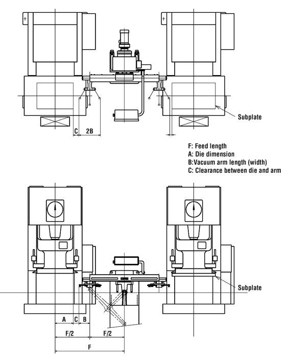
Setting up for robotic press-to-press transfer systems requires some press, tooling and workpiece considerations, such as distances, bolster height, and stroke length, as well as feed length and die clearance. Good preparation yields optimal productivity results and eliminates problems (see Figure 1).
Set up the press-to-press center in a range that is repeatable within ±0.5 millimeters (mm). The standardized distance will allow you to use multiple standard transfer robot models instead of custom units to make up for different press-to-press distances.
Set the bolster height in the range of ±0.5 mm. Pay attention to bolster parallelism and perpendicularity. Be careful of interference between the robot and the press control panel and operation panel.
You’ll need to install three or more spare rotary cam switches on the press side for signal connections between the press and robot—one for press in operation, another for press home position, and yet another for unloader command.
Select a press with the longest possible stroke to allow for sufficient room for the part to be lifted from the die and removed. If you are using a servo press, be aware that control methods vary from press manufacturer to manufacturer.
During press installation, position the intermediate table on the front side of the robot in a way that does not interfere with the robot’s movement. The intermediate table is a nesting location between presses for the part. The robot will place the part onto the intermediate table and the next robot will pick up the part and transfer it to the next press.
In a typical robot movement pattern (see Figure 2), the home position of the workpiece vacuum arm should be 1⁄4 of the press pitch. With this in mind, you should base the robotic movement selection on the largest die and the largest workpiece.
The typical robot cycle time is from 1.5 to 3 seconds.
The workpiece draw depth and the knockout stroke should be within 80 percent of the robot’s vertical movement length (see Figure 3).
Figure 1
This is a typical arrangement for the installation of a transfer robot between presses.
Feed Length. Feed length should be twice the maximum workpiece dimension. The maximum dimension of the vacuum or magnet arm is the value remaining after subtracting the die dimension from the feed length. When using the subplate for the slide underside for die standardization, however, you should determine the feed length based upon the subplate.
Feed Length, Workpiece Vacuum State. Select the feed length appropriate for the workpiece and die configurations, because the die size (the punch holder and the clamp) is limited by the feed length and the workpiece vacuum state.
Die Set, Guide Post, Clamp. Make sure there is appropriate clearance to prevent the robot fingers from interfering with the die or guides when they enter to pick up the workpiece. Likewise, the slide or subplate must not interfere with the fingers when the robot is in the home position. The robot cannot interfere with other equipment while it is in motion.
Unified Slide Center. Unify the slide center to stock in each process as a general rule, and avoid offset load conditions.
Part Pickup Magnets. When using magnets for workpiece pickup, float the workpiece 1 mm or more from the lower die to prevent magnetic force leakage to the die. Consider scrap floating prevention or scrap removal because the die may become magnetized.
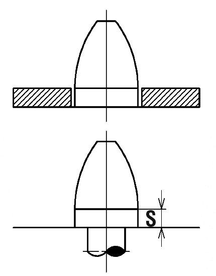
Workpiece With Base Hole, or Dummy (Pilot) Hole. Select the base hole and dummy pilot hole with as large diameters as possible and as far from each other as possible. The pin straight part (S) should be S ≥ t (with exceptions). Work guide surface roughness should be a minimum 12S. The pilot pin bombshell shape is considered suitable because it is a configuration that is easy to put in and take out from above (see Figure 5).
S = Straight length at base of the Pilot Pin, t = Material thickness
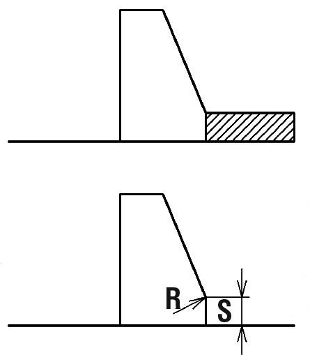
Pilotless Workpiece Positioning by Locator Guide, Strip Carrier. Some part configurations do not allow for a pilot hole to be located within the workpiece. A guide on the outer edge of the workpiece is used to guide it to its final position. The guide’s straight part S must be greater than the material thickness (see Figure 6). Work guide surface roughness must be a minimum of 12S.
As a general rule, the processed workpiece must always be left in the same position on the lower die.
Unstable Position After Processing. If the workpiece does not remain in position after stamping because of part trim or vibration, you can correct its posture and position by implanting a small magnet.
Figure 2
The home position of the workpiece vacuum arm should be 1⁄4 of the press pitch.
Attaching to Upper, Lower Die. Stabilize the robot’s unloading by using a kicker pin or urethane inserted into the die that helps separate the workpiece from the die. Consider the length of the kicker pin and urethane so that the workpiece’s pickup position is not altered.
Workpiece Lubricant Application. Apply the lubricant carefully. You should avoid lubricating the locations of the workpiece where the vacuum cups contact the material. Over time, lubrication can adversely affect the vacuum venturi pump’s performance. You must also avoid applying too much lubrication, as the vacuum or magnet can become too slippery for the robot to pick up, move and place the workpiece.
Punched Scrap. Be sure to separate the scrap from the workpiece. Do not leave scrap on the die or bolster.
Considerations for additional workpiece handling devices if required are:
Blank Feeding. The blank stacker/destacker and lifter must be able to handle the cosmetic requirements for the workpiece if required. It should be able to separate the blank into sheets and transfer them to the die without marring the workpiece. An indexing arrangement works best for blank feeding. An additional load station allows the press transfer line to run while blank material is replenished.
Turnover. A part turnover device must operate within the maximum workpiece dimension L x W. Deflection at a turnover for thin stock must also be taken into account as to avoid deforming the shape. The turnover process may be the limiting factor for speed attainment.
Unloader. The part unloader’s stroke length must be long enough to unload the workpiece completely from the die. Consider interference with the press operation panel when installing it to the press front. The feed length is roughly -101.6 mm, although it varies depending on the bolster or die dimensions.


The Fabricator is North America's leading magazine for the metal forming and fabricating industry. The magazine delivers the news, technical articles, and case histories that enable fabricators to do their jobs more efficiently. The Fabricator has served the industry since 1970.
start your free subscription
Easily access valuable industry resources now with full access to the digital edition of The Fabricator.

Easily access valuable industry resources now with full access to the digital edition of The Welder.

Easily access valuable industry resources now with full access to the digital edition of The Tube and Pipe Journal.

Easily access valuable industry resources now with full access to the digital edition of The Fabricator en Español.
In this episode of The Fabricator Podcast, Caleb Chamberlain, co-founder and CEO of OSH Cut, discusses his company’s...


