


A grand unifying theory of press brake bending: Part III
Considerations for aircraft applications as well as bottoming
Several months ago I introduced a new way of predicting the inside bend radius, a way that may help you attain ever more accurate bend calculations. To do this, we’re redefining a few common terms. Instead of the sharp-, radius-, and profound-radius bend terminology we’ve used in the past, we’re working with new terms and definitions, as follows:
- Sharp bends have a specified inside radius that’s generally 63 percent of the material thickness or less for 60-KSI cold-rolled steel. (For more on this, see “How an air bend turns sharp” on www.thefabricator.com.)
- Perfect bends have an inside radius that’s between 63 percent and 125 percent of the material thickness.
- Radius bends have an inside radius that’s greater than 125 percent of the material thickness.
I’m calling this the “Grand Unifying Theory” of radius, bend deduction, and die selection, and for this installment, we’re covering a specialty that’s unlike other areas of bending: the aircraft die.
What Makes an Aircraft Die an Aircraft Die?
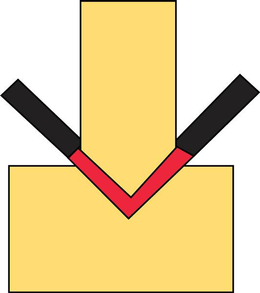
An aircraft channel die’s width increases with its depth, and that depth is about 120 percent of the die width. This allows enough penetration into the die to create a radius with a greater bend angle than 90 degrees complementary. This means that when the workpiece is bent so that it takes up the entire diameter of the die space, you still have an additional 20 percent clearance in depth—something that’s not present in a standard channel die (see Figures 1 and 2).
If you use a channel die for bends less than 90 degrees complementary, the aircraft tool will continue to work as a standard V die, just with a very small width-to-diameter ratio. In this case, you can calculate the opening and radius as if you were air forming in a standard V die rather than an aircraft die.
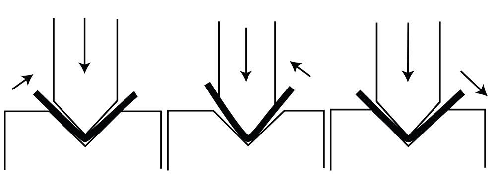
When the angle passes 90 degrees complementary in an aircraft die, a wiping process begins to take place (see Figure 3). At just past 90 degrees, a “hard” transition from air forming to wiping occurs, and at this point the bend may be a little unstable.
Between 90 and 180 degrees complementary, we need to factor in the punch nose diameter. Say we need to produce a 180-degree U bend in 0.062-inch-thick material, using a punch with a nose radius of 0.437 in. and a nose diameter of 0.875 in. First, we need to run a calculation that ensures we have enough material clearance between the punch nose and the die. Note that if we allowed only enough room for the material thickness on each side of the punch nose, we would create a high risk of wedging. That is, the material would become wedged between the punch nose and the aircraft die faces, creating myriad safety issues.
To account for this clearance, we incorporate 25 percent more material clearance on each side of the die. To do this, we allow space that’s 125 percent (or 1.25) of the material thickness on each side, and then double that figure to 2.5, which allows for extra space for the material on both sides of the die—hence the 2.5 figure in the clearance factor equation that follows:
This shows that we need a minimum die width of 1.030 in. to ensure we have enough clearance. In this case, the closest available die width is 1.062 in., which would be the best choice, as long as the tonnage for the job is within the limits of the tooling and the machine.
Note that multi-breakage can occur when forming with aircraft tooling as well, so there may be times when a urethane pad backup is in order, just as with a radius bend in a standard V die.
After we account for clearance and determine the ideal die width for our aircraft die, we next calculate for springback. Values for our current example, including the punch radius of 0.437 in., are converted to millimeters, per the formula:
Figure 1
In aircraft dies, the die depth increases with the width.
Measurements are in inches.
The original formula was developed for a 90-degree bend, and we’ve adapted it here for the increased springback in a 180-degree U bend (specifically, by multiplying the result by 2). Note that this formula is only an approximation at best—there are far too many variables to predict springback with total accuracy.
Regardless, now that we have approximated our springback, we can calculate our bent angle (or bent-to angle), which is the angle we need to reach before the punch releases pressure and the material springs back to our desired U bend of 180 degrees.
In previous columns in this series, we’ve worked with included bend angles, which meant that to calculate the bent-to angle, we subtracted the springback from the desired bend angle. So if we needed 90 degrees and had 2 degrees of springback, our bent-to angle would be an included angle of 88 degrees. Here, though, we’re talking about a 180-degree U bend. In this case, we add the springback to our bend angle to achieve our bent-to angle:
When the final bent angle exceeds 180 degrees, it may become necessary to use an additional urethane pad. With the correct durometer and pad geometry, it’s possible to reach up to an additional 20 degrees of bent angle, for a total maximum bent angle of 200 degrees.
Next, we need to calculate the radius. To simplify the math, we’ll head to www.handymath.com and click on “The Complete Circular Arc Calculator.” In this calculator, the “Height of Arc” variable is the outside bend radius, and the “Angle Subtended by Arc” is the bent-to angle.
This is the radius we achieve at the bent-to angle. But as we’ve discussed in previous columns, when the material springs back to a larger included angle, the inside radius becomes slightly larger as well. To uncover the springback factor, we divide the bent-to angle—that is, the angle you overbend to—by the bend angle (this applies when working with complementary angle measurements; for included angles, you divide the bend angle by the bent-to angle). We then multiply this factor by the radius we found from the “Height of Arc” measurement on the online calculator:
So now we have the inside bend radius after springback, which you’ll note is slightly larger than the 0.437-in. radius of our 0.875-in.-diameter punch.
Considerations When Bottoming
Bottoming is not coining. Coining occurs when the entire punch is stamped into the material at less than the material thickness (see Figure 4). Coining requires special toolsets and uses extreme amounts of force to create the bend, more than 10 times the amount required for air forming.
In bottoming, while the punch nose is stamped into the material, there remains an angular clearance between the punch and die angles. The bend attains 90 degrees at a point in the die space that’s about 20 percent the material thickness, as measured from the bottom of the V die. For instance, 0.062-in.-thick cold-rolled steel will bottom once the punch nose is 0.074 to 0.078 in. from the bottom of the V die (see Figure 5).
Bottoming also has high tonnage requirements, so it’s really best suited for light-gauge material. The inside bend radius is the same as the punch nose, less the bent-to/bend angle. Considering this, you can calculate the die width as follows:
Figure 2
In this sample selection of standard (not aircraft) channel dies, the depth does not change. Measurements are in
inches.
Note that bottoming in die widths other than a perfect bend isn’t recommended without special training, because of possible damage to the press and tooling, as well as possible operator injury.
Tying It All Together
Next month we’ll conclude our Grand Unifying Theory of bending with a review of the past few months and an outline of all the steps and formulas we’ve discussed. If you incorporate these steps, you’ll find that your bend calculations will become far more accurate. This means you will spend less time setting up the press brake and running tryout pieces, and more time actually making good parts.
Steve Benson is a member and former chair of the Precision Sheet Metal Technology Council of the Fabricators & Manufacturers Association International®. He is the president of ASMA LLC, 2952 Doaks Ferry Road NW, Salem, OR 97301, steve@theartofpressbrake.com. Benson also conducts FMA’s Precision Press Brake Certificate Program, which is held at locations across the country. For more information, visit www.fmanet.org/training, or call 888-394-4362. For more information on bending, check out Benson’s new book, The Art of Press Brake: the Digital Handbook for Precision Sheet Metal Fabrication, © 2014, available at www.theartofpressbrake.com.
About the Author

About the Publication
subscribe now

The Fabricator is North America's leading magazine for the metal forming and fabricating industry. The magazine delivers the news, technical articles, and case histories that enable fabricators to do their jobs more efficiently. The Fabricator has served the industry since 1970.
start your free subscription- Stay connected from anywhere

Easily access valuable industry resources now with full access to the digital edition of The Fabricator.

Easily access valuable industry resources now with full access to the digital edition of The Welder.

Easily access valuable industry resources now with full access to the digital edition of The Tube and Pipe Journal.

Easily access valuable industry resources now with full access to the digital edition of The Fabricator en Español.
- Podcasting

Seth Feldman of Iowa-based Wertzbaugher Services joins The Fabricator Podcast to offer his take as a Gen Zer...


