


Contributing Writer
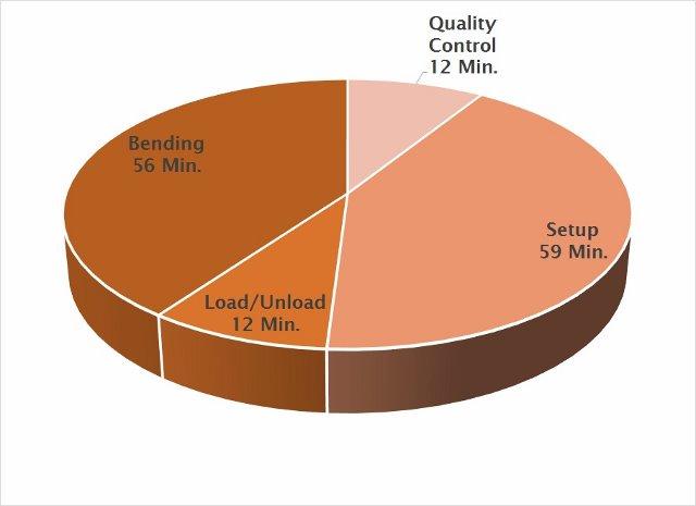
For a 50-part run, bending accounts for 40 percent of the production run (56 productive minutes out of 139 total minutes).
Figure 1 shows a breakdown of the time spent on an actual 50-part job. The process is composed of four elements:
Figure 1 illustrates the poor ratio of value-added time (changing the physical properties of the part) to nonvalue-added time (getting the machine ready to add value). In this example, 42 percent of the time needed to bend the parts is spent on setup.
In Figure 2, this poor result worsens when the lot size decreases to only five parts. At this point, the brake is producing parts approximately 10 percent of the time and earning no revenue 90 percent of the time.
Many companies have reduced lot sizes, or are considering it, but few understand the chaos that can result if proper systems are not in place to handle the increase in material handling, information flow, and setups.
The change in productivity is especially noticeable in the bending department. As lot size drops, the number of setups increases, resulting in a decrease in machine use. Unfortunately, smaller lot sizes do not mean that customers want fewer parts shipped. It means the same volume must be shipped, which requires a lot more setups.
In addition, managing setup information becomes much more critical when lot size decreases. Every metalworking company pays a price for setup.
With each setup comes information on how the job was done. If this information is not stored completely with easy access to the operator, it has to be re-created each time a job is repeated. If this is not done, the company ends up paying the full price of that setup every time the job recurs.
According to industry estimates, at least 50 percent of the jobs processed at a given shop are repeats, which emphasizes the importance of managing setup information.
| Setup Steps for Conventional Operation | |
|---|---|
|
A critical concept to understanding machine tool automation is external versus internal setup.
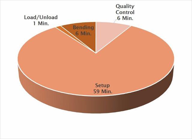
The ratio of value-added time to nonvalue-added time falls considerably as production runs get smaller. For this five-run part, the value-added time is a mere six minutes, which is less than nine percent of the setup and production time.
Internal setup traditionally is done only when a machine is down (e.g., when installing tools). External setup can be done while the machine is producing parts. Shifting internal setup to external is a key to boosting productivity. When internal setup can be shifted to external, machine tools have more time available to produce parts.
Perhaps more important than increasing production is that this shift makes short-run manufacturing more economically feasible.
When a part is programmed and set up conventionally, an operator receives a router and a part drawing. Prior to testing, setup material is delivered. At this point, beginning at step 3 (see Figure 3), the process becomes somewhat of a black art. In viewing a drawing, an operator mentally simulates the bending process. This happens in reverse order, starting with the last bend and working backward toward the first bend.
The sequence and tooling required are conceptualized and selected. This process can be like traveling through a maze--many false starts can occur. Die holders, dies, and punches are selected and installed in the press brake.
The setup and bending program then are tested. If the test part comes out incorrect, the operator has to go back to step 3, which is more common than some may want to admit.
Machines that process parts reliably, accurately, and consistently are critical to automation. To get the full benefit of automation, it’s important to reduce or eliminate any and all variables in the bending process. Seven common variables are:
One notable source of variation is in tooling. Conventional press brake tooling does not lend itself to automation because too much irregularity in tool geometry exists. Precision-ground tooling (sometimes referred to as European-style tooling) is much less irregular because of the manufacturing process used to build the tool. When tooling is dimensionally consistent, an electronic tool library that contains a description of the tools can be very effective for simulation purposes.

The Fabricator is North America's leading magazine for the metal forming and fabricating industry. The magazine delivers the news, technical articles, and case histories that enable fabricators to do their jobs more efficiently. The Fabricator has served the industry since 1970.
start your free subscription
Easily access valuable industry resources now with full access to the digital edition of The Fabricator.

Easily access valuable industry resources now with full access to the digital edition of The Welder.

Easily access valuable industry resources now with full access to the digital edition of The Tube and Pipe Journal.

Easily access valuable industry resources now with full access to the digital edition of The Fabricator en Español.
In this episode of The Fabricator Podcast, Caleb Chamberlain, co-founder and CEO of OSH Cut, discusses his company’s...


