


President
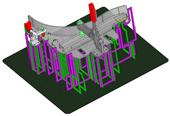
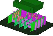
Figure 1: This fixture uses precision-cut plates, or “blades,” that support the workpiece. Note that the plate interiors are cut out. These help reduce fixture weight.
Welding fixtures can be expensive and complicated. Manufacturers often ask the question, How fast can I get a fixture, at what cost, and for what return? When fixturing can be done with quick, economical fixturing techniques, bidding on such jobs becomes attractive.
This is where technology comes into the picture. Mainstream 3-D CAD systems have enabled tooling designers to use solid-body subtraction (requiring processes like machining) to create a fixture model for any given manufacturing proc-ess. Such software-derived fixturing has played a part in machining applications for some time. For sheet metal work fixturing, depending on the component to be fixtured and the CAD system, this process sometimes can be quick and easy; but other times it’s not much better than traditional, manual fixture-building methods. Hard tooling for traditional fixtures often depends on costly milling and other non-sheet metal processes.
So how can this be minimized? The simple answer is to marry the processes and machinery you already have—including laser cutting, waterjet cutting, and punching—to the appropriate CAD system.
In high-product-mix, low-volume situations, fixturing can drive costs skyward. Consider robotic welding. Historically, such automation has been far more cost-effective for long runs. But just-in-time demands more flexibility and, thus, shorter runs. So where does this leave the welding robot? Fixturing challenges may prevent you from using the robot in short runs, so you end up using precious manpower to perform the welding and to make or source an expensive fixture. If you do use a robot, it may well sit idle while an expensive fixture is either made or sourced.
You can cut the hard costs out of both welding and fixture-building by using software to create the fixture quickly. Assume you have a short run that’s ordered every three months. By using a computer-generated fixture and subsequently saving the robot program, you can cut the fixture-design time drastically for subsequent runs, making the robotic method far more attractive. (Robots aside, creating fixtures in part or entirely with software also can increase efficiency of manual welding, for the same reason: Modeling your fixture in CAD reduces fixture-design time.)
Let’s say that three months go by and the job comes up again, only this time a slight upstream process change requires adjustment to the contact points between the fixture and the part. The technician can retrieve the original CAD model and make minor geometric changes to the fixture as needed. A new fixture component then can be made to replace an existing one.
When you program offline, you work with the ideal, mathematically perfect model. Real-world parts, of course, aren’t made to mathematical perfection, so you need a way to compare the perfect model with the real-world situation, and accommodate the robot program to suit. Depending on the robot model or whether there’s access to a probing arm, you can take a set of three XYZ coordinates. The system compares those real-world coordinates with those in the computer model, and then makes necessary programming adjustments to accommodate.
Such adjustments become critical for short-run, repeatedly ordered work. When the order comes up again, the system can use these sets of XYZ coordinates to compare the real-world situation with the stored robot program from the last run, so that the appropriate adjustments again can be made to the robot program.
For years fabricators have modeled fixtures in CAD, bringing fixture design out of the toolroom and onto the computer desktop. But this alone doesn’t overcome all challenges. It still takes time for the engineer to build a fixture on-screen. The tooling engineer can make his job easier by developing a library of common components—an Erector® set, of sorts, that allows him to design various shapes and supports with common elements. But once complete, the welding fixture may have a support bracket here, another block there—items that must be machined. Milling and turning are staple toolroom processes for a reason. They’re precise, and no manufacturing process can be precise without precise fixturing components.
These days, however, milling and turning aren’t the only options, especially in the contract metal fabrication shop. Processes like laser cutting, waterjet cutting, and even punching have become accurate enough to produce fixturing components. It also takes far less time (and, hence, costs less) to cut sheet or plate than it does to mill or turn. So instead of limiting yourself to a collection of traditional fixturing components, why not also use a series of precision-cut plates, or “blades,” to support an assembly to be welded (see Figure 1)? Once the blades are designed, software can export the blade profiles to DXF files for laser cutting, waterjet cutting, or punching.
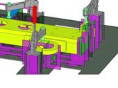
Figure 2: In this fixture, clip feet (at the bottom of the purple blade sections) slide and lock into slots on the base plate. This simplifies fixture assembly and disassembly and eliminates the need for spot welding.
This method can minimize or eliminate the machining required to build a fixture. Because the approach uses common components, it shortens fixture-development time for the tooling engineer. Like a 3-D jigsaw, fixture components interlock to create a part fixture. In essence, the blades’ upper edges mate to the underside and vertical (Z direction) edges of the solid parts, creating a cradle into which the part assembly can be placed.
Using standard plate components does simplify fixture design greatly, but variables remain, including the blade material gauge, size, base plate holes, and their positions. Certain software packages take these variables into account to automate the editing of fixtures. The software can import component parts into the system as solid bodies, and then bring users step by step through the fixture design. It can also import standard clamp CAD files (from companies like De-Sta-Co). All this allows the program to model the complete part and fixture assembly.
Consider the fixture design in Figure 2. A generic base plate can include slots at standard pitch intervals. Fixture blades then can be inserted into the base plate using “clip foot” tabs; picture rectangular tabs but with footlike extensions. These allow the blades to slide and lock onto the base plate slots. They not only eliminate the need for spot welding fixture components into place, but because the fixture has no welded joint, it can be quickly disassembled and stacked flat for storage.
Note the open “window” cutouts in the blades themselves, as shown in Figures 1 and 2. These windows reduce the fixture weight, which can make life easier for technicians who change out fixtures frequently for short runs. Such windows in the blade also help dissipate heat from welding, minimizing the slight material growth that can happen if fixture components endure heat input for prolonged periods.
The most critical part of the blade is the edge that contacts the workpiece itself. Not all blade edges are perfectly flush with the workpiece; if they were, the fixture would not be able to adapt to variability in part geometries, especially from bending processes.
Consider an edge of the blade that supports a part’s radius. Because of some unavoidable variability upstream, that bend might be plus or minus a few thousandths of an inch. To accommodate for this, the blade edge contacting the workpiece is made so that there is a gap (say, 0.050 in.) between the workpiece surface and the blade edge. At specified intervals are small “bumps” that bridge this 0.050-in. gap. If a part’s geometry varies slightly from the norm (though still within customer-specified tolerances), bumps can be ground down to suit. These bumps also help reduce the effects of heat on the fixture. If a part sat flush on a blade edge, more heat would be transferred to fixture components during welding.
These bumps may not always work for sensitive or soft materials, like aluminum. So for these applications, such fixtures can incorporate holding methods to reduce or eliminate surface scratches on the part. Say you have an aluminum box that you need to place in a steel fixture. Instead of small tabs or bumps, these blades have slots that can hold copper or plastic strips that can be weaved across the blades, as shown in Figure 3. These copper or plastic strips hold the workpiece so that the part emerges from the welding cell scratch-free.
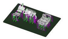
In some cases, the part may be welded in one fixture “cradle” location, with the welding gun able to access all required joints in one setup. In other cases, a part may require multiple cradle positions; that is, the part may be fixtured one way, welded, then repositioned on another fixture on the same base plate, as shown in Figure 4. Or one base plate could even be designed with several fixtures that hold dissimilar parts. To a large degree, the simplicity or complexity of the fixture design using this blade approach is determined by the fabricator’s imagination and job requirements.
Most significant, this method—combined with CAD software that can aid the fixture-design proc-ess—helps shorten fixture-build time dramatically and, hence, reduce costs. And, of course, the less time a shop spends building fixtures, the less time it will take for the company to ship quality parts out the door.

The Fabricator is North America's leading magazine for the metal forming and fabricating industry. The magazine delivers the news, technical articles, and case histories that enable fabricators to do their jobs more efficiently. The Fabricator has served the industry since 1970.
start your free subscription
Easily access valuable industry resources now with full access to the digital edition of The Fabricator.

Easily access valuable industry resources now with full access to the digital edition of The Welder.

Easily access valuable industry resources now with full access to the digital edition of The Tube and Pipe Journal.

Easily access valuable industry resources now with full access to the digital edition of The Fabricator en Español.
In this episode of The Fabricator Podcast, Caleb Chamberlain, co-founder and CEO of OSH Cut, discusses his company’s...


