


Software brings new intelligence to press brakes
 |
| Software with the capability to store and apply process intelligence enhances fabricators' ability to achieve first-part accuracy; reduce part waste; and meet demands for small lot sizes, short turnarounds, and complex shapes. |
To keep up with profound changes in the manufacturing environment, press brakes are getting smart. For decades these magnificent, hulking mechanical devices—capable of delivering thousands of pounds of controlled force—depended on the brains and memories of their skilled operators. Simply put, they were dumb machines made smart by proficient operators.
Those days are done. Dumb press brakes are dinosaurs, on their way to extinction. First, their masters—the skilled operators—are difficult to find and replace.
Second, many of the jobs dumb press brakes were best at—producing simple parts in high volumes—have migrated from the U.S. to low-cost labor regions offshore, unlikely to return. The types of press brake projects that remain in the U.S. tend to be those requiring smaller lot sizes, shorter turnarounds, and more complex shapes than those going offshore.
Enter Smart. Exit Trial and Error
Enter the need for smart press brakes—those with the capability to store and apply process intelligence. That intelligence comes in the form of software with open, PC-based controls that overcomes the limitations sometimes associated with CNC—insufficient memory, file name restrictions, lack of connectivity, and detailed setup information.
Today's shrinking lead-times and smaller lot sizes demand more frequent setups, which cut into production hours. Graphical machine controls and offline programming can help maximize operational time by eliminating the time for trial-and-error setup and improving first-part accuracy. The graphic capabilities are central to advanced PC-based controls, because they provide step-by-step, 3-D graphics and process menus.
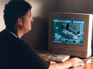 |
| Figure 1 Bend simulation software calculates the possible bend sequences and automatically checks for part interferences with tooling and machine components. |
Windows®-based software minimizes the need for special programming skills, making it possible for shops to take advantage of the forming expertise needed for complex and difficult jobs once provided only by setup specialists. This information then can be stored and accessed any time the same part needs to be run again.
Software upgrades can increase press brake productivity and improve accuracy by simplifying programming, speeding setups, incorporating automatic compensations, capturing and replicating best practices and process intelligence, and eliminating trial and error.
Simulation. Part bending process simulation enables tryout of part forming in a fraction of the time needed for an operator to do the physical setup and forming trials on the shop floor (see Figure 1). Bend simulation software calculates the possible bend sequences and automatically checks for part interferences with tooling and machine components. After the programmer accepts the simulation, the software automatically generates a part program, complete with optimized ram settings and backgauge positions.
Tool Libraries. Using a tool library to store tool dimensions enables an operator to calculate ram reversal positions automatically to speed up angle adjustments.
The software may allow the programmer to create custom tool libraries containing just those tools in inventory. This ensures that the program specifies only those tools with the correct cross section.
Tool library capabilities continue to expand. Some software provides utilities specifically developed for segmented tools. These utilities track tool segments stored in inventory and provide an autocalculate function to help a programmer determine the segment combinations needed to build a tool of the desired length, rather than cutting one to length.
Angle Mode. Smart software provides an angle mode for air bending that uses the material thickness value and the selected tool dimensions stored in the tool library to calculate the ram reversal position automatically. This eliminates the need for the operator to work out, on a trial-and-error basis, how deep the punch must penetrate the V die to produce the desired angle to compensate for material springback. Instead, an operator can calculate the starting point using a penetration of 0.4 times the V opening, then adjust per test bends on sample material.
Tonnage Mode. Light-gauge material often is bottom-bent with 90-degree or 88-degree dies, with the operator relying on experience to determine the ram reversal position. Software simplifies bottom bending by reversing the ram on a tonnage value instead of a position. In tonnage mode, the software uses the material thickness, type, and bend length, along with the V opening dimension stored in the tool library, to automatically calculate the tonnage required to bend the part.
Gauge Finger Library. In addition to stored tool dimensions, some control software now can store gauge finger dimensions to assist backgauge adjustments.
It is highly probable that a unique part shape will require a unique or customized gauge finger design. When a new finger is put into use, the finger's exact length is stored in the gauge finger library, where multiple gauge fingers can be stored.
When the operator selects a different gauge finger, the software references the exact finger dimension stored in the library, eliminating the need to calibrate the distance manually from the finger's gauge surface to the tool centerline.
Gauge Allowance Calculations. Like other steps of the programming process, determining the correct backgauge position requires experience. Part drawings typically show the flange length as either an inside or outside dimension. Since the backgauge position entered in the control is the distance from the bend line to the gauge finger, the final gauge position must be adjusted in or out to obtain the correct flange length.
Normally, the operator determines the adjusted amount, or gauge allowance. The accuracy of this adjustment is based on past experience or trial-and-error bending. To speed the process, some shops have created reference tables for their operators. Advanced software now automatically calculates gauge allowance values. The formulas used by the software to calculate gauge allowance can be customized for specific material types, thickness, K factor, bend radius, V opening, and flange type (inside or outside).
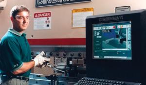 |
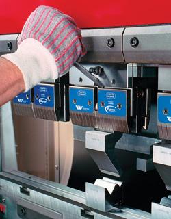
| Figure 2 On the shop floor, PC-based graphical controls and software can provide job setup instructions, including tool names, segment lengths, graphic displays of tool locations, and 3-D views of part-handling sequences to prevent forming errors. |
On the Floor, Out the Door
On the shop floor, PC-based graphical controls and software make it possible to capture and institutionalize best practices as standard operating procedures (see Figure 2). Step-by-step how-to graphics make visual instruction available on control displays, providing inexperienced operators with the equivalent of a resident trainer.
A part program can provide job setup instructions, including tool names, segment lengths, graphic displays of tool locations, and 3-D views of part-handling sequences to prevent forming errors. The payoff—press brakes are set up and parts are processed repeatedly with the same program settings, tools, and bend sequences, which is critical for reducing variation to meet tighter process and quality control requirements.
Software features have been developed to improve the first-piece accuracy of both bend angles and flange dimensions.
Three-dimensional graphics allow operators to see the part shape, gauge fingers, and tool sets available, as well as to preview each step required to form the part (see Figure 3). The graphics display the part orientation, bend sequence, and how the part shape changes at each stage. Visual display of the part orientation at each step helps prevent scrapped parts caused by incorrect bend sequences. This is especially suitable for complex parts that require multiple bends and staging of more than one set of tools.
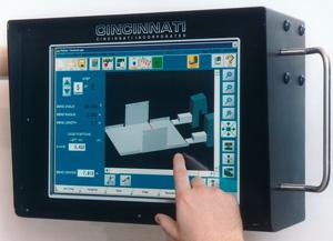 |
| Figure 3 3-D graphics allow operators to see the part shape and to preview each step required to form the part. The graphics display the part orientation, bend sequence, and how the part shape changes at each stage. The operator can rotate the view—up to 360 degrees—for a different angle or perspective just by dragging a finger across the screen. |
If any confusion exists about part handling, these graphics allow the operator to rotate the view—up to 360 degrees—for a different angle or perspective simply by dragging a finger across the screen.
Being able to save and recall programs, instead of having to create new programs, reduces the number of necessary adjustments. However, when using a saved program, knowing the actual material thickness is critical for first-piece accuracy. Because sheet metal mill thicknesses vary, a quick measurement (and adjustment) of the first-piece thickness is recommended. Doing so, rather than using the nominal thickness measurement stored in the program, could improve the first piece of the production run by two or three degrees.
In the effort to reduce cost, many shops today do not produce extra blanks for brake setup.
"However, if the first piece is severely overbent, the part may have to be scrapped. If no extra blanks have been produced, a one-off part order must be rushed through the shop.
Angle Corrections. These are made in angle mode by measuring and entering the actual angle produced from the last stroke. After the operator enters the actual angle results (best checked with a protractor), the software automatically calculates the adjusted ram reversal position. Entering the actual angle is much easier than guessing—in thousandths of an inch—how much ram position adjustment to make. The angle correction can be applied to all steps in the program or just the individual step.
Flange Corrections. When multiaxis backgauges are used, specifically, a gauge that has programmable left/right gauge fingers that travel along a gauge bar, flange corrections can be tricky. A good operator checks the flange dimensions on the left and right ends of the part to correct both the flange dimensions and parallelism. However, the gauge fingers are rarely positioned exactly over the top of the in/out drive screws. This requires the operator to guess at how much the drive screw positions should be adjusted to make the flange accurate and parallel.
Software simplifies this task. Because the software knows both finger positions on the gauge bar, an operator just enters the actual left/right flange dimensions produced during the last stroke. The software will do the math and reposition the drive screws, taking into account the distance the gauge fingers are from the drive screws.
Tool Overload Protection. An increasingly important and costly part of the forming process is tooling, as fabricators may spend premium dollars for tooling that is accurate and fast to set up.
Most press brakes, however, have no knowledge of the tools installed. Using only his judgment, the operator loads tools, and then sets the ram reversal position to make the desired angle. There are no safety checks to determine if the tools will withstand the forces generated when the punch pushes the metal into the V die. This sometimes overloads and breaks a tool, such as a gooseneck punch or narrow V die.
In addition to storing cross-section dimensions, the tool library also can store maximum loading values, entered as tons per foot, that the tools were designed to withstand. If a tool's maximum load capacity is reached during forming, the ram will immediately reverse, protecting the tool from overload and the operator from potential injury.
Batch Software. This type of software allows multiple jobs to be ganged and bent in a nonstop process. Batch software is particularly suited for jobs that share common material, thickness, and tooling. For example, multiple parts nested on a single sheet from a laser or punch press can be formed on the press brake in the desired order and quantity, with minimal setup and programming.
Batch software allows multiple programs to run automatically in sequence, without requiring the operator to open and start each program individually. Batch processing can reduce setup time between jobs, increase part production per shift or day, and shorten processing time on JIT orders, while enabling tighter and more accurate work scheduling. Batch processing is ideal for manufacturers that regularly run repeat parts.
Adaptive Material Compensation. This type of software optimizes the speed, economies, and flexibility of air bending by using on-the-fly compensation technology to overcome the effects of material variations, which can cause inaccurate bend angles. The software calculates material thickness and strength during each bend, then adapts to changes by automatically adjusting the ram reversal position to deliver a precise bend angle in one ram stroke at production speeds.
Want more information?<<<<<<<< Are you looking for ways to improve your press brake processes to eliminate time that doesn't add up? Read "Taking a long-term view of press brake productivity". |
It does this by collecting readings from strain gauges and encoders on the press brake during the forming portion of the stroke. As the material reaches the yield point, the software calculates material thickness and strength. The ram then continues through the bend and reverses at its newly calculated reversal position, without pausing or slowing down.
PC Revolution
The PC revolution is making it possible for software to bring greater process control, application tools, and productivity to bending operations. Fabricators have a rich range of software tools available for reducing setup times, variability, trial and error, and operator intervention. Therefore, software can raise press brake output and operator proficiency, enabling fabricators to produce more good parts with higher precision, less rework, and less scrap.
Todd Kirchoff is product manager, Cincinnati Incorporated, P.O. Box 11111, Cincinnati, OH 45211, 513-367-7510, fax 513-367-7592, todd.kirchoff@e-ci.com, www.e-ci.com.
About the Author
About the Publication
subscribe now

The Fabricator is North America's leading magazine for the metal forming and fabricating industry. The magazine delivers the news, technical articles, and case histories that enable fabricators to do their jobs more efficiently. The Fabricator has served the industry since 1970.
start your free subscription- Stay connected from anywhere

Easily access valuable industry resources now with full access to the digital edition of The Fabricator.

Easily access valuable industry resources now with full access to the digital edition of The Welder.

Easily access valuable industry resources now with full access to the digital edition of The Tube and Pipe Journal.

Easily access valuable industry resources now with full access to the digital edition of The Fabricator en Español.
- Podcasting

In this episode of The Fabricator Podcast, Caleb Chamberlain, co-founder and CEO of OSH Cut, discusses his company’s...


