


Vice President of Advanced Forming
Although hydroforming has become a relatively common manufacturing process in recent years, it formerly was reserved for high-volume parts because of the high price of entry—presses and dies don’t come cheap. As tool designs have become more economical and development costs have dropped, this technology has spread to lower-volume applications with much success. The advantage of combining multipart, formed shapes into single components made with fewer process steps is a benefit that is hard to overlook.
In the early days of its widespread use in the automotive industry, hydroforming was an alternative process; components were converted from other processes to hydroforming. Eventually it earned a higher profile in the manufacturing industry when engineers began designing components specifically for the hydroforming process. As time went on, advances in finite element analysis (FEA) software and material databases made the process more predictable.
Of course, tube hydroforming has limitations that engineers and designers must keep in mind when evaluating a potential part. The starting form of a tubular hydroformed part most often is a prebent tube that is placed into the hydroforming tool. The hydroforming tool halves close and a hydraulic press holds them together; specialized plugs, commonly called docking rods, seal the tube ends; and, as the part fills with fluid, servo-hydraulic feed actuators, which often are synchronized with the pressure profile during the forming process, drive the docking rods, feeding the tube into the press (see Figure 1).
Pushing the material into the dies during the forming process increases the ability of the material to elongate, as compared with just stretching (without the pushing action). Expansions of more than 100 percent are common, but not along the entire length of the tube—very high expansions typically are localized near the feeding area of the tool. If the tube is prebent to fit into the tooling, or precrushed, work-hardening comes into play and reduces the total amount of elongation. Annealing often is used to restore ductility to the material, thereby improving its ability to elongate. In some cases, annealing is used between the forming stages.
The following equations help to illustrate the limitations of the tube hydroforming process. These are rough calculations but can be very helpful in determining forming forces and pressures.
Estimated press tonnage required:
F = pA/2,000
Where:
F = The minimum clamping force required (tons)
p = The maximum forming pressure (pounds per square inch [PSI])
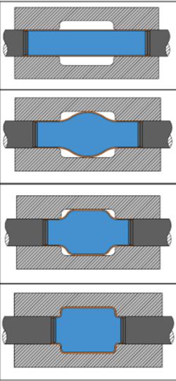
Figure 1: The hydroforming process consists of four stages. (1) The blank is placed into the die, and docking rods seal the ends. (2) The intensifier pressurizes the blank, and the docking rods feed the material into the die. (3) The internal pressure and the simultaneous feeding of the material form the tube. (4) The pressure increases to calibrate the tube (the process of filling in the corners and other difficult-to-form features). The finished product has essentially the same profile as the die cavity.
A = The final plan area of the finished part, as defined at the tool parting line (square inches)
When the tube is pressurized, the material’s yield strength determines when the tube begins to stretch plastically. The following equation estimates the pressure required to start the forming process:
Minimum forming pressure estimate:
Pmin = (YS)t/r
Where:
Pmin= The burst pressure of the tube (PSI)
YS = The yield strength of the tube material (PSI)
t = The wall thickness of the tube (in.)
r = The radius of the tube’s ID (in.)
The smallest feature to be formed determines the necessary forming pressure. Keep in mind that hydroforming has some limitations as to the smallest formable feature. For example, a sharp corner is impractical; a radius is required.
The final pressure required to form the part, filling in the smallest features, is the calibration pressure. Experience, FEA, and experimentation often are required to determine the calibration pressure accurately. Engineers should bear in mind that the calibration pressure often is much higher than the burst pressure of the tube. Although this seems counterintuitive, the tube doesn’t burst because it’s supported by the die.
The following formula estimates the burst pressure of a tube:
Pb = (UTS)t/r
Where:
Pb= The burst pressure of the tube (PSI).
UTS = The ultimate tensile strength of the tube material (PSI)
t = The wall thickness of the tube (in.)
r = The radius of tube ID (in.)
These simple formulas can be manipulated to predict the pressure required to form some of the small features. To do so, substitute the radius of the feature (r) for the tube’s ID in the previous formulas. Keep in mind that these are estimates; many factors come into play that affect the final outcome.
Every hydroforming project requires a careful analysis of the material’s elongation to prevent excessive thinning, which can lead to parts that don’t meet functional tolerances or parts that rupture in service. A simple length-of-line calculation often is sufficient for cases in which the part simply is being stretched into a different shape, or being resized. Typically, FEA
determines this more accurately than a length-of-line calculation.
The two critical material characteristics are the minimum yield strength (MYS) and the ultimate tensile strength (UTS). These are the points at which the material starts to stretch and the point at which it tears, respectively. How can engineers reduce the MYS and UTS, thereby increasing the amount the material can stretch? Turn up the heat.
Almost all metals exhibit increased elongation and reduced MYS and UTS when heated sufficiently. The trick is finding the temperature that provides the best combination. This often is called the material’s superplastic temperature. Superplasticity can be defined as very high, uniform elongation. When heated to its superplastic state, the metal’s MYS and UTS decrease dramatically, while its ability to elongate increases significantly. Aerospace component manufacturers have used this process for aluminum and titanium alloys for many years. The drawbacks are that true superplastic forming requires exotic alloys, tight temperature control, and extended cycle times.
To take further advantage of increased plasticity and allow the use of standard alloys, high-temperature metal gas forming (HTMGF) has emerged in the past decade. This process takes advantage of the material’s forming characteristics at very high temperatures, approaching 90 percent of the alloy’s solidus temperature. Like cold hydroforming, the process is suitable for high- and low-volume production and has a rapid cycle time.
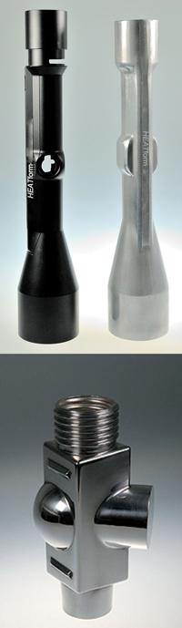
In this process, the tube or pre-formed shape is preheated to a very high temperature, then transferred to a heated tool and processed in a very similar method, using gas as the pressure media instead of a water- or oil-based fluid (see Figure 2). HTMGF has two chief advantages over hydroforming. First, because the material’s pliability increases substantially in its superplastic temperature range, the process allows the forming of much finer part details. Second, the process works at lower pressures. In some cases, the press tonnages, feed actuator forces, and forming pressures are just 10 percent of those used in hydroforming at room temperature.
The tradeoff is that HTMGF requires more equipment than hydroforming. In addition to a press to hold the die halves shut, these systems require a preheating source for the blanks, heated tooling made from materials that can perform at these extreme temperatures, a precisely controlled high-pressure gas system, specialized sealing tools for the blanks, and precise feed actuator and pressure controls.
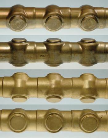
Investigating a specific part, one made by both hydroforming and HTMGF, can be helpful in understanding the difference between these two processes (see Figure 3). In this case, the alloy specified by the customer didn’t have good cold-forming properties, so forming the part required several hydroforming stages.
This isn’t to suggest that HTMGF is superior to hydroforming. Just as hydroforming is an alternative to other manufacturing processes for some components and assemblies, HTMGF is an alternative to hydroforming when the process suits the application. In addition to forming tight-radius features, it is beneficial when alloys that do not have superior cold-forming properties come up short.
Choosing the optimal process often is a matter of considering both hydroforming and HTMGF early in the design stage when simple modifications to the part to aid the manufacturing process are easy to incorporate, similar to adding a draft to a molded or cast part. Although HTMGF still is new to many people, it has been used for high-volume automotive parts for the past several years, and industrywide acceptance continues to grow.


The Tube and Pipe Journal became the first magazine dedicated to serving the metal tube and pipe industry in 1990. Today, it remains the only North American publication devoted to this industry, and it has become the most trusted source of information for tube and pipe professionals.
start your free subscription
Easily access valuable industry resources now with full access to the digital edition of The Fabricator.

Easily access valuable industry resources now with full access to the digital edition of The Welder.

Easily access valuable industry resources now with full access to the digital edition of The Tube and Pipe Journal.

Easily access valuable industry resources now with full access to the digital edition of The Fabricator en Español.
Seth Feldman of Iowa-based Wertzbaugher Services joins The Fabricator Podcast to offer his take as a Gen Zer...


