


New Product Development and In-Die Engineer
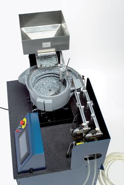
A hopper containing bulk fasteners feeds into a bowl; the bowl feeds the fasteners into a track; and the track feeds them into the tooling, which then singulates them and sends them to the press as the press calls for them.
Editor's Note: In-die joining systems help stamping shops to expand their operations to include subassemblies and full assemblies without additional downstream equipment and processes, so they can carve out a bigger share of the production work.
This is a two-part article. Part I focuses on in-die fastener feeding systems that install fasteners during the stamping process. Part II covers in-die laser welding.
Broadly defined, a self-clinching fastener is any threaded device that, when pressed into ductile metal, displaces the host material around the mounting hole, causing it to cold flow into a specially designed annular recess in the shank or pilot of the fastener.
A serrated clinching ring, knurl, ribs, or hex head prevents the fastener from rotating in the host material once it has been properly inserted. Thus, self-clinching fasteners become a permanent part of the panel, chassis, bracket, or other item into which they are installed.
1. Feeder. First, bulk fasteners have to be oriented the same way. Then they have to be singulated and sent to the press one at a time. The feed system uses vibratory bowls, hoppers and inline tracks.
The bulk fasteners flow from a vibratory hopper in a cascading effect into a vibratory bowl. When the press calls for a fastener, it is singulated out to a track and pneumatically blown to the die.
High-low sensors in the track sense when the track runs low on fasteners, and will signal to the vibratory bowl to then orient more nuts or studs to go into the track. As the bowl gets low it will then call the hopper to put more parts into the bowl, so it's a pull concept rather than push concept.
So a hopper containing bulk fasteners feeds into a bowl; the bowl feeds the fasteners into a track; and the track feeds them into the tooling, which then singulates them and sends them to the press as the press calls for them.
2. Controls. Most people think of controls in terms of what they want to happen, but really, it's also a matter of when, similar to graphing X and Y variables.
If you know the speed and acceleration profile of the press, and you are looking at sensor transitions during that stroke, then you can monitor the press stroke from both position and time and also degrees of press rotation.
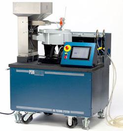
In terms of installation, once the die is completely built and in daily production, the stand-alone system can be hooked up within three to 10 minutes. Everything is quick-coupled and twistlock-connected.
The main concept revolves around an array of flag sensors, mounted within a flag sensor block, that indicate time and position. Generally, the flag sensor block is mounted to the bottom die shoe. A notched flag rod, usually mounted to the top die shoe, telescopes in and out of the flag sensor block as the press cycles, tripping these sensors in a specific sequence. Because the press is running at a constant cycle speed, you can discern timing and position from the trip of the sensors based on flag rod travel.
Now you know where the die is within its cycle, and that information is sent back to the feeder system to tell it when to fire a fastener—or if it's too late to fire a fastener. Basically, as the rod is on its way up as the press opens, a sensor turns off, and that gives what is called the shoot window during which the fastener is fired. As the press closes, the rod starts to telescope back down and the notch on the rod will signal the sensor to turn on, which closes the window.
So the fastener should fire during the top part of the stroke and actually be installed at the bottom of the stroke.
3. Tool Heads. For successful in-die fastening, removable in-press tooling is paramount. Dies that incorporate in-die fastening usually are very large. They're difficult to move around and open. Because press time is very valuable, quick change of these components is necessary.
It's important that the in-die system have modular construction and in-press accessibility. So if a problem occurs and the press stops, within 15 minutes you should be able to swap out a whole modular tool assembly and put another one in.
4. Inspection. From a few sensors, you can glean all kinds of information. For instance, say the strip doesn't advance properly and the hole is not in the right position for installing the fastener. As the press closes and the strip comes down, a pin associated with this sensor does not enter the hole and is pushed down, tripping the sensor. The sensor and pin verify that the hole is present and in the right location before the fastener tries to go in.
If the pin does not go in, you know that either the punch broke and no hole is present or the strip didn't advance; you know that this will not be a good installation.
The way the system works is as the flag sensor calls for a fastener, the fastener is pneumatically singulated and blown from the feed cart into the press on the upstroke. On the downstroke, the fastener is installed. As the press opens again, the inspection occurs on the bottom of the stroke and so the press knows to keep going. As the press opens, it calls for the next fastener.
Material Thickness. Clinch fasteners were developed for thin sheet applications. They are especially suitable when good pullout and torque loads are required in sheet metal that is too thin to provide secure fastening by any other method.
However, they work equally well with thick sheet applications. There is no material thickness limitation for in-die fastening, other than the thin sheet limitation of the fastener. The low end of the material thickness spectrum is about 0.8 mm thick, but that is more a function of the fastener than it is of the in-die system.
Fastener Commonality. The other criterion is commonality of fasteners. It is not practical to have different types of fasteners coming out of the same vibratory bowl. It is not technically impossible to set up several vibratory bowls, but there is a point of diminishing dollar return, because the bowl is the most expensive part of the feed system.
Feeding six different fasteners is technically possible, but then you need the capability of feeding six different parts. And so that means six vibratory bowls, and six hoppers, and the ROI is just not there.
Generally, a vibratory feed bowl feeds the same fastener, for example, an M5, M6, or M8. There can be two systems, one for nuts and one for studs. Four feed lines can come off one bowl, so you can feed the same fastener type at four positions within the die. Using quick tool change, you can switch from an M5 to an M6 or an M8.
Volume. Although there really is no technical limitation regarding fastener size or quantity, there is a cost consideration regarding whether in-die fastening is economically feasible. Are your volumes high enough to offset the initial cost? Based on productivity, about 250,000 fasteners is a typical minimum quantity break-even point. On a four-up system (four feed lines) that would mean feeding 75,000 parts to achieve a good return on investment (ROI).
Speed. About 60 strokes per minute (SPM) is the upper limit on speed. Technically, an in-die system can work at higher speeds, but the expense curve goes up. When a feed system operates faster than one insertion per second, the strategies to accomplish it incur expense.
Stroke Length. Because a fastener is loaded while the press is opening, about 6 in. of stroke is minimal to allow enough time for the fastener to enter the die.
An example of a part that is not suitable is a flat part blanked on a high-speed press running at 2,000 strokes an hour with 1/2 in. of stroke. It is not feasible to try to feed fasteners that quickly with such a short stroke.
So a typical application is one or two types of fasteners inserted with about 6 in. of stroke and at about 60 SPM, with a minimum quantity of 250,000 fasteners. Outside of that realm, it is probably not cost-effective.
Complexity. Circumstances other than productivity, such as part complexity, may drive a need for in-die fastening; for instance, if the formation of the part does not allow access to the hole after the part is formed (see In-die Part Accessibility sidebar).
Being able to install the fastener during part forming offers a broader range of design capabilities for components because if you don't have access to the hole, you don't have to consider how you'll insert the fastener after the part is formed.
Quality. Another consideration is that any secondary operation lends itself to human error, such as mixed parts and so forth. So inserting the fastener while you're stamping the part eliminates potential downstream problems.
Project Development. Generally, a cost analysis is performed. The preliminary part print and die design are examined. What does the part look like? What is the die going to look like? And from there tooling is developed that fits that application via an exchange between the die designer and the in-die design engineers using 3-D modeling, STEP files, engineering drawings, and documents.
A design review is paramount because everything has to bolt together just right. Once the design is finalized, metal is cut and the die is built.
The inside of a die is a very difficult environment—things like wires are subject to damage. So all the sensors lead back to the junction box inside the die, and a multipin connector goes back to the feed system as part of the die. You just plug into it.
Once the die is completely built and in daily production, you literally can hook up within three to 10 minutes. Everything is quick-coupled and twistlock-connected. The feed systems just require shop compressed air and standard line voltage. No more energy is required than a toaster.
Multiple Utility of Components. Part of robustness is simplicity. The thinking is to critique the process to see if it can be done with fewer components. Can I get one component to do two jobs? By reducing the number of components and complexity, you can reduce costs and increase robustness. So from a cost standpoint, which is always a driver, the more applications a component can perform, the faster ROI can be achieved.
One fastener may not be exactly like another fastener, but they may have certain aspects in common, so maybe there's an in-between design that can accommodate both. If you can produce those common parts in higher volume, then their cost drops. Efforts are on condensing the design to meet many applications and insert a variety of fasteners but with fewer parts and more commonality of parts.
Vision Systems. Another trend is the greater use of vision systems. After the component is completed and it comes out of the press, a vision system inspects many features of the entire part—fasteners are just one of them. In-die fastening benefits from that technology.
In-die fastening doesn't work in a vacuum. It has to fit into your current shop conditions. You can have a great system, but if it's not user-friendly and simple to maintain, then it's a great idea that doesn't really pan out.


The Fabricator is North America's leading magazine for the metal forming and fabricating industry. The magazine delivers the news, technical articles, and case histories that enable fabricators to do their jobs more efficiently. The Fabricator has served the industry since 1970.
start your free subscription
Easily access valuable industry resources now with full access to the digital edition of The Fabricator.

Easily access valuable industry resources now with full access to the digital edition of The Welder.

Easily access valuable industry resources now with full access to the digital edition of The Tube and Pipe Journal.

Easily access valuable industry resources now with full access to the digital edition of The Fabricator en Español.
In this episode of The Fabricator Podcast, Caleb Chamberlain, co-founder and CEO of OSH Cut, discusses his company’s...


