


3-D CAD design communication skills
Some ways to communicate design ideas to the non-CAD design reviewer
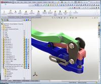
Figure 1
Design review meetings are critical to the success of any product development project. The 3-D CAD model is effectively the first prototype. Design review gives everyone involved a chance to catch errors, omissions, and gaps between vision and reality.
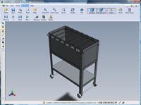
When the meeting can be held with everyone huddled around the 3-D CAD workstation, the expert in charge of the software can spin the model around, hide and reveal components, and slice cross sections to help the others to assimilate the goals and reasoning behind the model. Figure 1 shows an example of a typical 3-D CAD session.
If a face-to-face meeting can't be held—or rather a face-to-3-D model—then it is incumbent upon the 3-D CAD crew to produce other kinds of documents to communicate the same information.
3-D CAD File Exchange
Sometimes the design reviewer will have access to the same software that was used to create the 3-D model. That can be a mixed blessing. The blessing is the opportunity to examine the model just as the original author created it. The curse is the risk of accidental edits of parametric relationships.
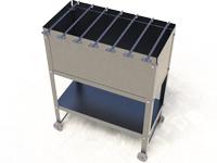
A good solution is to convert the model to a "dumb solid" by using an intermediate file exchange format. This is also a solution for situations where the design reviewer has an alternate brand of 3-D CAD software. Figure 2 shows an example STEP file; textures and modeling history probably will be lost, but the details of the shape are complete.
The decision as to which file format to use depends on the software in use. STEP is reliable and is an effort to update the well-established capabilities of IGES, also a widely accepted exchange format. Parasolid® is probably the most reliable, but is very 3-D CAD-specific.
Web Meetings
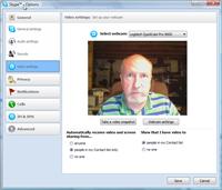
This is a topic worthy of its own column. Webinars, hosted Web meetings, and desktop sharing are powerful tools for bringing minds together. Figure 3 shows a screen capture of the author using Skype™, which is low-cost—with many features being free—and packs a lot of functionality.
I have found online design review meetings to be productive if all of the participants actually participate. The temptation of participants to multitask during an online meeting is my only knock against this kind of endeavor.
3-D Viewers
If the design reviewer is willing to install some software, then 3-D viewers can be handy. They allow nearly the same spin, zoom, hide, and cross-sectioning tools that the native 3-D CAD software has. Read-only viewers also prevent any accidental editing. It is also likely that the files exchanged can be smaller in size than the original 3-D CAD modeling file.
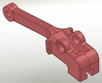
Figure 2Exchange files like STEP are useful for protecting the design and sharing the model among various 3-D CAD software packages.
The 3-D CAD software that I use includes a free viewer-only version, and it operates exactly the same way as the full 3-D CAD version. That may require more training than the design reviewer is willing to put up with, but it offers a great opportunity to see the model in the same way as the original author.
An excellent 3-D viewer system is eDrawings™ (see Figure 4). The viewer is free; the publisher software is purchased. Operating the eDrawings viewer does require some training, but the operation is nearly intuitive—most people become "expert" in just a few minutes. It allows for markup and measurement, and file sizes are very compact.
3D PDF is a good way for the design reviewer to study the outer surfaces of a model. The 3D PDF viewer requires practically no training. The file sizes are large, and the limitations can be frustrating—no cross sections, no hide/ show, no measurement, and so forth.
Pretty Pictures
If the design reviewer does not have access to 3-D viewing software, then the production of 2-D documentation is necessary. Images don't move, but they do allow the author to focus the attention on a particular aspect of the design. Figure 5 draws your attention to the way the skewers rest on the frame.
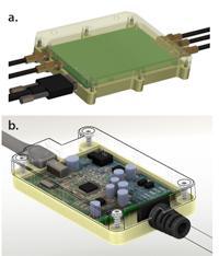
Screen captures are easy to produce either with tools built into the 3-D CAD software or with software like HyperSnap™ or Snagit™. The transparent display of the cover in Figure 6a reveals how the connectors attach to the circuit card. In Figure 6b the strain relief on the cord is easier to see with the cover shown in wireframe mode.
I've recently become enamored with PhotoView 360™ for producing nearly photo-realistic images very quickly. That is how Figure 5 was made. The degree of realism that you put into the image is a tricky balance between schedule and "wow" factor. When selling a design idea, "wow" is a blessing.
Gerald would love to have you send him your comments and questions. You are not alone, and the problems you face often are shared by others. Share the grief, and perhaps we will all share in the joy of finding answers. Please send your questions and comments to dand@thefabricator.com.
About the Publication
subscribe now

The Fabricator is North America's leading magazine for the metal forming and fabricating industry. The magazine delivers the news, technical articles, and case histories that enable fabricators to do their jobs more efficiently. The Fabricator has served the industry since 1970.
start your free subscription- Stay connected from anywhere

Easily access valuable industry resources now with full access to the digital edition of The Fabricator.

Easily access valuable industry resources now with full access to the digital edition of The Welder.

Easily access valuable industry resources now with full access to the digital edition of The Tube and Pipe Journal.

Easily access valuable industry resources now with full access to the digital edition of The Fabricator en Español.
- Podcasting

In this episode of The Fabricator Podcast, Caleb Chamberlain, co-founder and CEO of OSH Cut, discusses his company’s...
- Trending Articles
1
Capturing, recording equipment inspection data for FMEA

2
Tips for creating sheet metal tubes with perforations

3
Are two heads better than one in fiber laser cutting?

4
Supporting the metal fabricating industry through FMA

5
Omco Solar opens second Alabama manufacturing facility
