


Ph.D.

An automated optical metrology system with a laser scanner gathers millions of points in 3-D space from the surface of the hood of a new vehicle during a check on sheet metal stamping and forming tools–the "build event"–as part of readying the vehicle for production. Image courtesy of Perceptron Inc.
Automakers spend millions of dollars and countless hours developing a prototype for each new product. By using the latest virtual building tools, they—and other manufacturers—can reduce the cost and time spent in development while improving quality.
Dr. Richard J. Gerth, an independent research scientist, and Product Line Manager Michael Bourgeois of Perceptron sat down with interviewer Jack Thornton to answer some questions about automakers' challenges and the role of virtual building tools to help solve them.
Gerth: Yes. High-strength steels are great from a designer's perspective, because they combine lighter weight with greater toughness for the most demanding forming and drawing operations that form automotive body panels. But they can be hell on manufacturing operations, which must produce mating parts to very tight gap and flush specifications and on stamping dies and forming tools.
Gap and flush dimensions have a huge impact on the appearance of vehicle exteriors, and because they are critical to buyer perceptions of vehicle quality, the specs are exacting. Specifically, gap is the distance between a door edge, for example, and its opening in the body—a few millimeters with a very tight tolerance. Flush refers to the vehicle's aerodynamically smooth line from the front fender to the rear quarter panel.
The difficulty is in predicting work hardening and springback in these high-strength steels. All stamped, drawn, and formed steels work-harden and spring back toward their original shape to some degree.
Optical metrology—laser scanning, white light, photogrammetry—can be used to characterize large and complicated surfaces such as body sides, doors, hoods, roofs and roof pillars, and deck lids accurately and completely.
Analyzing the 3-D points—point clouds—generated by these optical surface inspections can reveal what happens to a panel's dimensional properties as these high-strength steels are formed.
Understanding the changes in those properties is the key to small but critical die design improvements. That understanding also can reduce costs and save time associated with die tryouts as new vehicles are put into production.
Beyond this, the automotive industry and its tooling suppliers are wrestling with using optical metrology to digitally "close the loop" between the sheet metal coming out of the tools and the CNC machine tools that recut die surfaces, ever so slightly, until the panels fit together as designers intended.
Ultimately, this is an issue of automatically morphing the CAM programs that were used to machine the dies and tools in the first place or, maybe more accurately, generating programs that have built-in springback compensation.
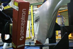
Figure 2. An automated optical metrology system with a laser scanner gathers millions of points in 3-D space from the surface of a deck lid of a new vehicle during a check on sheet-metal stamping and forming tools. Image courtesy of Perceptron Inc.
Gerth: The way that high-strength sheet, blanks, and coils behave as they are formed into vehicle exterior panels and some interior components. In engineer-speak, the material behavior is "nonlinear"; it changes as a function of part geometry and, more importantly, as a function of how much it is stretched. Physical properties of these steels vary between suppliers and batches, which adds to the challenges.
Moreover, because of the nearly universal use of high-strength steels for structural components, few if any of the large, complicated assemblies are 100 percent within nominal specifications. Thus, the visible exterior panels, which must follow the dimensions of the underlying structural assembly, will not look right in terms of gap and flush.
Ensuring that the sheet metal of each new vehicle will fit is a demanding exercise. All the panels that go into a vehicle body are brought together in one location to uncover and fix problems between mating parts. In particular gap-and-flush analyses show what needs to be adjusted in each part and its tooling.
What results after tens of millions of dollars spent (and weeks of time consumed on the critical path to production launch) is a physical, functional prototype of the vehicle's body-in-white, which is the fully assembled sheet metal.
The image in Figure 1 demonstrates the advances in simplicity and clarity between the conventional point-by-point inspection methods with CMM data and CMM road maps (paperwork at left) and the optical metrology image at lower right. The part shown at upper right is an inner hood.
Gerth: The extra costs are concentrated in a series of build events for the structural components of passenger vehicles and light trucks and die tryout. Significant funds and several weeks in the all-important vehicle launch schedule go for one-off, custom-designed fixtures. These events involve simulating the assembly tooling to be used in production. They also determine which of certain panel features need to be changed and by how much. Normally the final build event for each new vehicle is held at or near the assembly plant.
Much time is spent recutting to tweak die surfaces. Each die tryout cycle and machining takes two to four weeks and may have to be repeated several times.
Optical metrology (Figure 2) may render much of this unnecessary, dramatically reducing the cost of a production launch and getting new vehicles to dealer showrooms several weeks sooner.
Die tryouts are a big deal. In a recent article in Automotive Design & Production magazine, Gene Stefanyshyn of GM was quoted as saying 113 tryouts were needed to "get it right" for the rear quarter panel of the 2010 Camaro® sports car. Forming that panel requires a huge, 164- mm draw.
If ever there was a challenge of getting everyone together in one place, that was it. The car was designed mostly in GM's engineering operations complex in Warren, Mich., but it is produced in Oshawa, Ontario, Canada. Design input came from Russia, Korea, and Brazil. And Stefanyshyn, GM vehicle line Executive in charge of performance cars, is based in Australia.
Figure 6. Changes in a typical draw die punch surface are shown here before and after rework using Digital Body Development System (DBDS) processes. Changes in the outer flange area are intended to remove unwanted crowning and raise the surface of the hinge pocket. After rework, about 73 percent of the overall die area changed less than -0.1 mm. As with much rework, the resulting surface was not left-right symmetrical; mirror point locations varied by as much as 0.5 mm. Image courtesy of University of Michigan Transportation Research Institute (UMTRI).
Gerth: Sheet metal fit-up and die tryout are among the few trial-and-error processes remaining in manufacturing. And like most other trial-and-error processes, they are yielding to computer simulation.
Software now is readily available to fit up a vehicle's sheet metal. The software digitally locates, orients, and matches all the panels in the virtual world, inside a computer, where costs are low, rather than in the high-cost physical world.
Optical metrology is a substantial improvement over even the best of today's methods for sheet metal panel characterization and fit-up. Those methods rely on coordinate measuring machines (CMMs).
It doesn't matter whether the CMM is a multimillion-dollar clean-room system that can check an entire vehicle body in one setup (and several hours) or a $100,000 portable unit.
CMMs use touch probes and gather points on sheet metal surfaces one at a time—a few hundred points in an hour or two. A few hundred points can never fully characterize surface twists, edge curls, overcrowns, and so forth, in high-strength steels.
With CMMs, inspectors have to search through hundreds of points on lists and grids for meaningful trends in springback, which is critical to gap and flush analysis.
Aside from good eyesight and number-crunching skills, inspectors' only analytical "tools" were plus and minus signs for points above or below the nominal surface of the panel. From this scant information, they had to form a mental picture of the panel as it came out of the tooling.
It took many years to develop the skills necessary to perform CMM inspection. Now many of these technicians are being laid off or pushed into retirement.
Gerth: That's a very large part of the difference, yes. Optical metrology gathers a million 3-D points (Figure 3) in space in a few minutes, tens of thousands of times more than a CMM can, and in a tiny fraction of the time. These 3-D point clouds accurately and completely characterize surfaces. Engineers and toolmakers no longer have to guess at overcrowns, twists, curls, and springbacks.
The virtual assembly of mating parts in nominal vehicle position relies on those point clouds. Assembling those parts in nominal vehicle position is a simple, fast, and effective way to uncover interferences—overlapping panels—as well as any gaps between panels that are too wide or uneven. For this to work, every aspect (size, orientation, and form) of every mating surface feature, no matter how subtle, must be captured. Only optical metrology can do that.
Image courtesy of University of Michigan Transportation Research Institute (UMTRI).
For previous generations of steels that behaved in a linear fashion—predictable work hardening and springback—a few hundred points probably were sufficient. But even for steels that behaved in very linear fashion, that data was too sparse for CAM programmers to use directly.
So it was interpolated back into solid models before it could be sent to the programmers.
That interpolation is time-consuming and prone to human error. It also generally meant that toolmakers had to put the die sets and forming tools back on their mills and re-establish the original machining setups, a daylong process often repeated several times.
If the tooling had been made overseas, difficulties multiplied. Specialized tooling shops, mostly in the Detroit area, took the recut work on a rush basis and priced accordingly.
Gerth: The industry already uses optical metrology to generate new CAM programs manually, and that has dramatically speeded up die tryout. When automakers use these methods together with virtual die buildup, die part inspection, and virtual die spotting (which ensures the proper gap between the top and bottom dies), die tryout time can be cut by as much as 75 percent, from 40 weeks to 10. Achieving this has taken three to four years of focused, collaborative effort between suppliers and automakers.
The industry can go a lot further, and to get rid of build events, we will have to. With scanned data we can tweak die designers' solid models automatically. Standard CAD/CAM integration tools, such as associativity, can help quickly regenerate machine tool programs for recuts.
Some data-handling standards to do that already exist. A few other areas need more work.
Gerth: Most of the technical issues were addressed by the DBDS initiative. DBDS was a virtual functional build of a vehicle's exterior sheet metal—the digital equivalent of the physical body-in-white prototype (mentioned earlier) using scanned 3-D surfaces.
From that, DBDS developed predictive models of the assembly process, verifying the fits, gaps, and flushes with optical metrology. As the program wound down in 2008, the next goal was to use those predictive models to modify die surfaces as they went into recutting.
DBDS was a five-year manufacturing research program managed by the Center for Automotive Research (CAR), an independent nonprofit in Ann Arbor, Mich. Participants included Atlas Tool, Diversified Tooling Group, Ford Motor Co., General Motors Corp., Hexagon Metrology, Perceptron, Siemens PLM, TechTeam Government Solutions, the University of Michigan, and Wayne State University.
We [Gerth and Bourgeois] were active in DBDS. The federal government put up one-half of the DBDS $10.6 million budget. Among other things, this highly pragmatic effort revealed that using point clouds from optical metrology offered a practical approach to adjust and refine die surfaces (Figure 4 and Figure 5).
DBDS raised some fundamental questions. First, do we even need to conduct build events if we have sufficient inspection data on the stamped parts? Maybe not. Second, production systems and tooling have always envisioned sheet metal panels as rigid, but they are not. They range from flexible to springy to downright floppy and always have.
DBDS addressed these challenges with finite element modeling and analysis (FEM/FEA). The idea was to pinpoint which specifications had to be relaxed, which ones needed to be tightened, and whether no-build conditions could be detected digitally in the software. CAR used Siemens Teamcenter® Vis VSA software to build simulation models of the body assembly process.
DBDS also showed that feeding optical metrology data back to the tooling shops' CAM programmers was superior in time and cost to using CMM touch-probe data.
Examples of DBDS research can be found in Figure 6, Figure 7, and Figure 8.
Gerth: Ford and GM, but hardly anyone else, at least not on company time, because of the woes of the economy. But this too shall pass. When it does, expect the automakers and manufacturing engineers to zero in. The applicable technologies, starting with optical metrology, offer too many advantages to be ignored.
Which is not to say, we're done here, not at all. Further refinements are still needed in die tryout. But those are in the realms of advanced data analysis, FEA, materials science, and the choice of testing systems. For example, in some advanced high-strength steels and applications, grain direction is important. Some testing systems pick up grain direction and others do not. This would be a good follow-on effort to DBDS.
Gerth: Optical metrology speeds up everyone's understanding of what is going on with the steel as the panel is formed. Point-cloud processing software lets everyone "see" this in great detail from any angle, any orientation.
Optical metrology systems let tooling engineers see the location and magnitude of any problems clearly. The opportunity is to use optical metrology as front-end input to the process of finalizing stamping, forming, and drawing tools for these large components. As always, tremendous gains in time and money flow from eliminating guesswork (no matter how "educated") and trial-and-error methods, no matter how well they seem to have worked in the past.
One of the main aspects of DBDS was combining the optical metrology data with the simulation tools to help manufacturing. Simulation tools have been the purview of design for a long time and still are. Manufacturing uses data analysis extensively, but simulation much less so. Bringing the power of data analysis and simulation together to improve manufacturing was a goal of DBDS.
A major advantage of being able to do virtual build events based on actual panel measurements would be the reduction in logistics—sending all parts to a central location at the same time. Virtual build analysis based on actual part data could be performed at any time by anyone anywhere in the world as soon as data on parts become available.
Depending on the purpose of the analysis, data on specific parts would be needed, but data on the entire vehicle might not be necessary. CAD files could be substituted for the physical parts if data were not available. Virtual build analysis could support globalization, the introduction of "world" car platforms, and multiple vehicle launches in different markets, as well as ongoing die maintenance.
These concepts are also being applied to other materials and processes that are reducing vehicle weight and boosting fuel economy—advanced high-strength steels, aluminum, magnesium, engineered plastics, and composites. Because of the difficulty in forming some of these materials and the lack of experience in working with others, build events will continue to be an important process to ensure the assembly quality of the body-in-white.
Virtual build will only help organizations learn faster and at lower cost how to achieve the required quality in these new, multimaterial bodies. These concepts are also being applied to interior trim components.
Even in these uncertain times for automakers, reducing launch times gets new vehicles into dealership showrooms sooner, when they command the best profit margins. That pulls up the automakers' returns on investment in new vehicles.
Carmakers will always need panel matching before launching production. The question for the foreseeable future is whether it will continue to be done physically and at great cost, or move on to better, faster, and cheaper virtual methods.
Richard Gerth, Ph.D., Ann Arbor, Mich., is an independent research scientist of automotive manufacturing engineering and technology. Michael Bourgeois is product line manager for AutoScan®, Perceptron Inc., Plymouth, Mich., www.perceptron.com.
Interviewer Jack Thornton, MINDFEED® Marcomm, Santa Fe, N.M., can be reached at 505-690-0828, jackt@mindfeed.com.


The Fabricator is North America's leading magazine for the metal forming and fabricating industry. The magazine delivers the news, technical articles, and case histories that enable fabricators to do their jobs more efficiently. The Fabricator has served the industry since 1970.
start your free subscription
Easily access valuable industry resources now with full access to the digital edition of The Fabricator.

Easily access valuable industry resources now with full access to the digital edition of The Welder.

Easily access valuable industry resources now with full access to the digital edition of The Tube and Pipe Journal.

Easily access valuable industry resources now with full access to the digital edition of The Fabricator en Español.
In this episode of The Fabricator Podcast, Caleb Chamberlain, co-founder and CEO of OSH Cut, discusses his company’s...


