


Sales Engineer
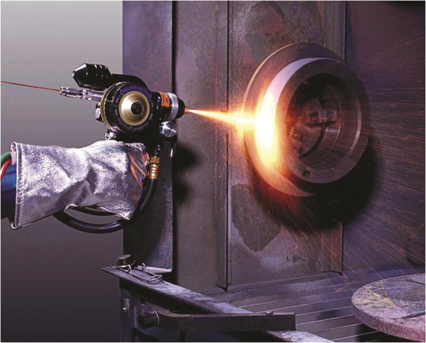
Figure 1
This thermal spray application uses a combustion source as the delivery mechanism.
Thermal spray processes generate a range of contaminants that threaten worker health and safety if not properly controlled. Is your facility at risk?
To understand what may be at stake, you need to know just what is happening during the thermal spraying process. It is an industrial coating process that involves melting material, usually in a powder or wire form, in a heat source, such as a flame, and then spraying the tiny droplets onto surfaces at high velocity (see Figure 1). Several variations of thermal spray exist, and most involve different equipment, materials, gases, powders, and wires. Because of its high deposition rate, the process is often used to apply thick coatings over a large area.
The real risk comes from the fine dust particles generated during the process. The best way to address this risk is to have a dust collection system that is specifically engineered to your thermal spray application (see Figure 2). This results in a system that minimizes risks and ensures regulatory compliance.
These dust particles can contain a variety of metals with potential health risks. The primary route of entry is the respiratory system. Other possible routes are eyes, ingestion, and skin contact.
Material Safety Data Sheets (MSDS) are a good starting point for identifying which metals occur in your processes. OSHA has established permissible exposure limits (PELs) based on an 8-hour time-weighted average for hundreds of dusts, including the numerous metals generated during thermal spray operations.
Nickel is the most commonly encountered allergen and is classified as a potential occupational carcinogen by the National Institute for Occupational Safety and Health and as a carcinogen on the International Agency for Research on Cancer and National Toxicology Program lists. Exposure to nickel and nickel oxide may cause metallic taste, nausea, tightness in the chest, fever, and allergic reactions. Long-term overexposure may cause lung fibrosis or pneumoconiosis. The eyes and skin also may be affected.
Cobalt exposure can trigger skin diseases, such as contact eczema and dermatitis, and respiratory irritation or decreased pulmonary function with diffuse nodular fibrosis. It is a potential occupational carcinogen for humans and can interfere with the metabolism of thyroid hormones.
Copper exposure is associated with eye irritation and decreased respiratory functions, with the appearance of cough and dyspnea. It is classified as a potential occupational carcinogen for humans.
Prolonged inhalation of aluminum may provoke respiratory problems, from a simple cough to acute pulmonary edema. Some rare cases of pulmonary fibrosis have been reported.
Hexavalent chromium, also called chromium VI or hex chrome, is a carcinogen with a long list of adverse health effects. It can be produced by plasma arc; flame, including high-velocity oxygen fuel (HVOF); and electric-arc spray processes. Almost any chromium-bearing material can produce the hexavalent state when exposed to the high energy levels associated with thermal spraying. Chromium oxide, MCrAlY, and nickel chrome are among the materials that produce hex chrome when sprayed.
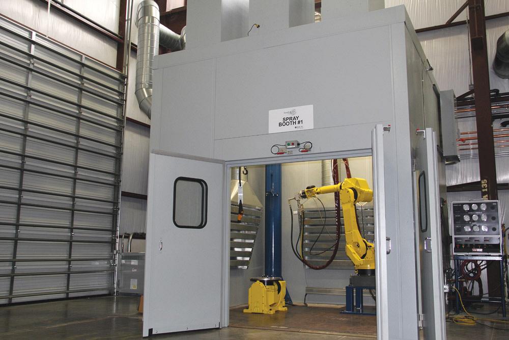
Figure 2
This thermal spray booth is specifically designed to work with the high-velocity oxygen flame process, which involves a flame, and the plasma arc process.
Hex chrome overexposure can result in short-term upper respiratory symptoms and eye or skin irritations. Long term, the greatest health danger associated with hex chrome exposure is lung cancer. Other major health effects include damage to the upper respiratory system and allergic and irritant contact dermatitis. Respiratory tract problems can include inhalation damage to mucus membranes, perforation of septum tissue between the nostrils of the nose, and damage to the lungs. In addition, injury to the eyes, skin, liver, and kidneys is possible.
The current OSHA PEL for hex chrome is extremely stringent, at 5.0 µg/m3 (micrograms per cubic meter). Respirators and controlled clothing are required for individuals who are exposed above this threshold.
Conduct air sampling to characterize worker exposure to airborne contaminants and determine whether metal fumes, dusts, gases, and vapors are at concentrations that exceed allowable limits. Ensure that workers are not exposed to exhaust gases from the thermal metal sprayer’s power generator. Some companies take it a step further and have employees take blood tests to ensure the levels of metal are not affecting their health.
Workers’ inhalation or other absorption of harmful metal dusts is a critical concern, but it is not the only concern. In the right concentrations, metal dust particles in the air
also can create an explosion hazard. Dust samples should undergo testing to determine combustible and explosive properties. Explosibility testing is essential in identifying the best dust collection system for an application as well as the explosion protection or prevention equipment to use on the dust collector and related components. Various factors, such as the metal’s purity and the presence of byproducts, moisture, and oxides, may affect the explosivity of an alloy’s dust.
A hazard analysis, conducted by an engineer knowledgeable about the process, also needs to identify the full range of combustible dust deflagration, fire, and explosion hazards specific to the application. Methods for hazard analysis relating to metal dusts are spelled out in NFPA 484: Standard for Combustible Metals. Readers also are urged to become familiar with the recently published NFPA 652: Standard on the Fundamentals of Combustible Dust, which introduces the concept of Dust Hazard Analysis (DHA), a new, simplified methodology targeted at factories involved in more basic processes involving simple dust collection systems.
Powder and dust control are mainly provided by the dust collection system. However, some issues are more specifically related to booth structure and controls.
The booth design needs to be linked with good ventilation flow and control. During the early design decisions regarding booth, coating box, or hood design, the layout can have a major impact on the ability to establish good ventilation flow and the ability to conduct spray waste powder to the filtration system.
Booth layout has a direct impact on the following ventilation concerns.
Airflow and Velocities. The booth layout affects total airflow capacity and determines velocities. Air velocities have a significant impact on the dust collection system’s ability to capture dust particles and carry them into the ductwork leading to the filters, rather than having them settle and accumulate on the booth floor, walls, and tooling. Improper or excessive airflow can affect spray patterns and flame direction.
Negative Pressure. In a properly designed dust collector, the exhaust fan creates a negative pressure on the booth itself. While booth doors are closed and the system is operating, this negative-pressure condition prevents dust/air from escaping the booth.
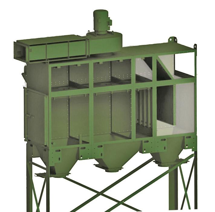
Figure 3
A drop-out module, shown right above the main collector area in this model, enhances cleaning efficiency by capturing a large quantity of dust before it reaches the primary dust collector.
Laminar Flow. The smoothest possible flow of air helps to ensure effective removal of dust from the process area, carrying it into the ducts leading to the dust collector filters. Turbulent flow may create eddies and low-pressure areas that cause dust to be trapped or dropped from the airstream.
Entry Timer. A timer is recommended to prevent entry into the booth until a preset time has elapsed after the shutdown of the process. The entry timer should allow enough time to clear the air of hazardous material.
When designing an exhaust system, you should evaluate each process and the output of the process intended for the spray operation. In particular, shops that rely on the thermal spray process need to consider the following with the design of a dust collection system:
• Gases. The gases used and produced vary depending on the thermal spray process. HVOF is a combustion process that uses explosive or combustible gases and oxygen. A plasma gun mainly uses inert gases, but also can use hydrogen, which is an explosive gas. A dust collection system can be used to prevent the buildup of the combustible/explosive gases. Under no circumstances can the buildup of combustible products be allowed in any spray booth as the thermal spray process itself is a guaranteed source of ignition.
The total flow of gas should be considered in the calculations used to determine the necessary ventilation airflow as well as the booth size. The gas types, booth dimensions, and dimensions of the parts being sprayed also should be taken into account to determine ventilation airflow. The types and forms of materials used in the spray process and their associated hazards also vary. Other items that should be documented during the design phase are listed in the Check List for System Design sidebar.
• Reaction byproducts (exothermic). The gases, materials, and powders used in thermal spraying can generate various reaction byproducts that must be considered in the overall design of the integrated thermal spray system. For example, water vapor can condense from the exhaust gases of a combustion process and come in contact with dust particles, such as aluminum dust, that have accumulated in the air handling and filtration systems. This interaction can release hydrogen gas, resulting in a potentially explosive or flammable condition. Air should not be recirculated back inside the building or back into the booth. In addition, exothermic reactions can occur, resulting in sufficient heat buildup to start a metal fire. Also, metal powders can form complex metallic compounds (such as hexavalent chromium or nickel carbonyl) as a result of their exposure to the high temperature of the spray process.
• Heat. Thermal spray processes produce excess heat that can elevate the exhaust air temperatures. The heat in the process can be diluted by the presence of airflow inside the booth. Insufficient airflow inside a booth may result in dangerous exhaust air temperatures. (When a booth is not present and a source-capture system is used, it is important to bleed in ambient air.) It is recommended that air temperatures never be allowed to exceed the design specifications of the filter cartridges.
Filtration is obviously an important component in a properly working dust collection system. You need to keep in mind these factors that influence filtration performance:
Air-to-cloth (A/C) ratio refers to the amount of air or process gas in cubic feet per minute (CFM) entering a dust collector, divided by the square feet of filter media in the collector. A higher A/C ratio allows the use of a small dust collector with low initial cost, but it will likely result in performance problems and shorter filter life. Overly high A/C ratios can cause dust to bypass the filters and be released into the atmosphere.
Because of this, conservative A/C ratios are recommended for cartridge dust collectors in thermal spray operations. Electric-arc (twin-wire arc) spray generally produces a high volume of fumes, smoke, and overspray. Lower A/C ratios are required to handle these conditions without blinding or plugging the filters. If excessive dust and fumes produced in any thermal spray process blind the filters, the air volume in the system and the carrying velocity in the ductwork decrease.
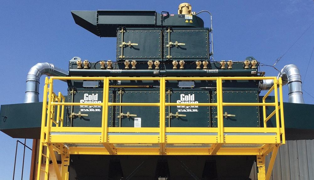
Figure 4
This dust collector for a twin-wire arc application is equipped with secondary high-efficiency particulate air (HEPA) filters, which are integrated on top of the collector to enhance dust capture.
When it comes to filter media selection over the past decade, nanofiber filter media has emerged as a popular choice. It combines high performance with long life. Fine-pored nanofibers act as a prefilter to the base media, capturing most of the dust at the surface before it embeds in the filter. This technology further increases a filter’s dust capture efficiency while also enhancing cleaning ability and service life.
For thermal spray applications, nanofiber media filters with an efficiency of 99.995 on 0.5 microns and larger by weight are recommended to meet EPA, state, and local regulations on industrial plant emissions. The media also should be flame-retardant.
Prefiltration modules, such as cyclones and drop-out modules, can be used in addition to dry media filters to enhance cleaning efficiency by enabling the capture of larger amounts of dust entrained in the airstream before it reaches the primary dust collector (see Figure 3). These modules also can function as a spark arrester by trapping large and hot particles that could otherwise damage the primary filters or send an ignition source into the collector.
A cyclone works by swirling the dirty air in a downward direction around the outside of a spiral path and then pulling the air straight up the middle. Large particles are forced down into a collection drum, unable to travel upward with the air. The overall efficiency of dust removal is rather low, but these devices excel at removing large amounts of particulates and can be used for product reclamation.
A drop-out module attached to the collector or positioned before the collector offers similar benefits to a cyclone. Drop-out modules tend to have a lower pressure drop and slow down the velocity of the airstream before entering the dust collector. They also can reduce the total cost of ownership of a collector by extending the life of the filter cartridges. Drop-out boxes before the collector take up minimal space and are easy to install and add to existing modular-design dust collectors, but they must be maintained regularly.
Though cyclones and drop-out boxes can extend the life of the primary filters, reduce fire risks, and aid in product reclamation, they also may increase fan horsepower requirements for a subsequent trade-off in energy costs.
Secondary filter systems—sometimes called an afterfilter, final filter, or safety monitoring filter—are often recommended for use downstream of the primary filtration system. They also often are required for applications involving the handling of certain hazardous powders and metals, such as nickel and chromium, and where that exhaust air is discharged to the atmosphere.
Traditionally, ductwork and a transition section have been required to connect this secondary filter module to the dust collection system. More recent integrated designs are available in which the safety filter is mounted on top of the collector, reducing installation costs and saving floor space. This configuration also allows the filters to be located prior to the fan, keeping them under negative pressure. Some newer designs also have been proven through testing to function as flame arresters for combustible dusts.
Safety monitoring filters use high-efficiency particulate air (HEPA) filters to enhance the dust capture efficiency of dry systems and provide backup protection if an air leak through the primary filters should occur (see Figure 4). Air is passed through the media to capture 99.97 percent of fine particles as small as 0.3 microns. These units must be used in conjunction with regular dust collectors, as they are not designed to handle large volumes of particulate and fumes.
Because of gaseous byproducts such as ozone, carbon monoxide, and nitrous oxide generated by thermal spray processes, experts do not recommend air recirculation downstream of the dust collector as a general practice. However, in special circumstances, the use of a safety monitoring filter system might allow air to be recirculated through the facility to reduce heat loss and save on energy in cold climates. Additionally, in some instances a heat exchanger used in conjunction with a dust collector may allow safe recirculation of air in a thermal spray application. Such systems require careful design and close operational monitoring to ensure safe operation.
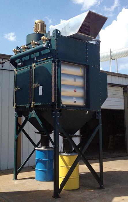
Figure 5
Whenever possible, the dust collector should be placed outside. This allows the explosion vents to be directed away from workers and equipment. In this photo, a dust collector used on a spray and fuse application incorporates an explosion vent and isolation valve to combat the possibility of an explosive situation.
Of course, any manufacturing company involved in thermal spray is likely interested in some guarantee of filter efficiency and emissions performance. Fortunately, they can rely on industry measurements or old-fashioned written guarantees.
Sometimes a dust collector equipment supplier may state that a system offers 99 percent filtration efficiency at a certain particle size or that it uses MERV 15 filters. These ratings are useful for comparing different systems, but mass density efficiency, defined as the weight per unit volume of air, is the best predictor of a filter’s compliance. The EPA, OSHA, and other regulatory bodies don’t care about percentage efficiency claims: They want to know that emissions will be at or below required thresholds, typically stated as grains per cubic foot or milligrams per cubic meter.
In the end, however, it may make sense to have the supplier provide a written guarantee of performance stating that the dust collector filters satisfy applicable emission requirements. That makes it clear what the end goals of the system design should be.
Manufacturers don’t want to think about the possibility of explosions that result from the wrong mix of dust particles and thermal sources, but it is a real concern. That’s why it’s crucial that the dust collection system have the right components to prevent this danger.
Explosion vents are required for all thermal spray processes. Usually located outside, these vents direct the internal pressures of an explosion in the dust collection system away from workers and equipment (see Figure 5). Explosion venting is covered in NPFA 68: Standard on Explosion Protection by Deflagration Venting.
If a collector must be placed indoors, the design must allow the explosion vents to direct pressure and flame fronts safely out and away from the building and its occupants. Another alternative for indoor installations is to use costlier explosion prevention equipment instead of venting.
A mechanical backdraft damper is designed for installation in the inlet ducting. The damper uses a mechanical barrier that is held open by the process air and is slammed shut by the pressure forces of the explosion. When closed, the mechanical barrier isolates pressure and flame fronts, preventing them from being able to propagate further up the process stream, protecting both the process and workers. Be sure to use a device that is compliant with NFPA 69: Standard on Explosion Prevention Systems.
Depending on local fire codes, a sprinkler system or other type of fire suppression system may be required. Also, to reduce fire hazards, remove combustibles from the work area and remove or isolate any ignition source not required for spraying with exhaust ventilation.
Designing a collection system to control dust and gases shouldn’t be based on hunches. Accurate data is needed to ensure the system performs as originally intended. The following information should be documented during the design phase:


The Fabricator is North America's leading magazine for the metal forming and fabricating industry. The magazine delivers the news, technical articles, and case histories that enable fabricators to do their jobs more efficiently. The Fabricator has served the industry since 1970.
start your free subscription
Easily access valuable industry resources now with full access to the digital edition of The Fabricator.

Easily access valuable industry resources now with full access to the digital edition of The Welder.

Easily access valuable industry resources now with full access to the digital edition of The Tube and Pipe Journal.

Easily access valuable industry resources now with full access to the digital edition of The Fabricator en Español.
In this episode of The Fabricator Podcast, Caleb Chamberlain, co-founder and CEO of OSH Cut, discusses his company’s...


