


President
Nowhere in manufacturing is the axiom "Do the job right the first time" more true than in a shipyard's welding operation. The welding process must be optimized for high productivity, yet maintain quality levels required by stringent welding standards.
Even using the most fine-tuned process, a welder can be done in by upstream operations that prepare the material for welding. New welding automation equipment is available that can be used before, during, and after welding to maximize productivity, reduce variability, and ensure high quality.
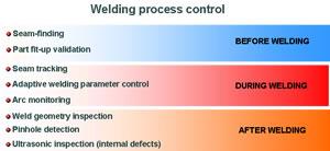 |
| Figure 1 |
Six Sigma welding refers to the efforts necessary to reduce the defect rate to less than the acceptable industry level of 3.4 parts per million (PPM). Achieving this standard requires nearly perfect joint repeatability, or as an alternative, intelligent automation.
When the manufacturing process and automation are considered early in the project, the chances for successful welding increase tremendously.
Three of the biggest issues preventing more widespread welding automation use have been (1) excessive gaps between parts, (2) unrepeatable joint locations, and (3) accessibility problems. Assuming that an honest effort to address these issues has been made, we now can turn our attention to the best way to apply automation.
 |
| Figure 2 Principles of Laser Vision |
Figure 1 identifies different sensors and equipment that can be used at each stage of your operation to ensure Six Sigma-level welding.
Figure 2 explains the principles of laser vision used for both joint tracking and joint and final weld inspection. The correct system must be selected with respect to camera field of view and resolution, as well as software options needed, such as adaptive control.
Currently almost all ships and boats are fit up and assembled manually. In addition, little material preparation or welding is automated. Typical roadblocks to welding automation have been large structures requiring big expensive welding equipment; low volume, which means automation prep takes longer than the welding; and part fit-up is not consistent enough. Now fabrication shops can considersome feasible solutions, beginning with preparing plate edges.
 |
| Figure 3 Preparing a weld joint using plasma gouging |
Manually preparing plate edges almost always results in excessive variation because of incorrect bevel angles and less than straight edges. A portable robot equipped to prepare the material edge accurately using cutting or gouging equipment can be beneficial in this area. See Figure 3 for an example of a portable robot equipped to cut the plate edge and inspect the preparedweld joint.
After the plates have been fit up, the portable robot can inspect the joint geometry to ensure it is within the tolerances specified by the welding procedure. If it is not, it will reject it at this point or indicate to the welder what he needs to do to correct the excessive variation.
Traditional fabrication methods have employed mechanized welding systems such as simple tractors and side beam carriages. Occasionally, and mostly unsuccessfully here in the U.S., articulated and gantry robots have been tried. (See Figure 4 for an explanation of different levels of automation and where the portable robot fits.)
Tracking and inspecting welds can be performed by equipment ranging from large gantry systems traversing panel lines half a football field long to small, portable robots that can be used for a variety of applications. In fact, in some shipyards, a portable robot is used first to splice together individual plate until a complete panel is completed. The panel then is moved under a large gantry,where laser vision is used to guide the welding system, so the stiffener to panel weld joint is followed correctly.
 |
| Figure 4 Shipyard automation categories |
Figure 5 shows a large gantry system. The portable robot is targeted at the job performed now manually or with a simple tractor. The advantage of using the portable robot during welding lies primarily in its ability to be programmed to accommodate non-linear joint issues and to minimize the need to locate the track exactly. Integrating a laser vision camera adds even morecapability to the system by allowing it to handle joint volume variation by tracking the joint and even offering adaptive welding capabilities. The current, voltage, and current travel speed all can be changed in real time to optimize welding conditions in response to a changing weld joint.
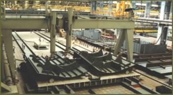 |
| Figure 5 Large gantry system with laser vision camera to track stiffeners |
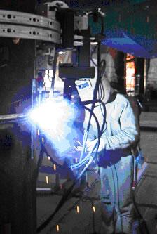
Portable robots can be used in all positions, including vertical, as shown in Figure 6. They are easy to use and quick to set up. All arc welding processes—flux cored arc welding, gas metal arc welding, and shielded metal arc welding—are compatible with this equipment. Any standard power source can be integrated with the portable robot so that all operations can be activatedfrom the robot teach pendant.
Conventional weld quality assurance procedures involve a combination of inspection methods. Depending on the joint type and the component criticalness, inspection methods can include visual, penetrant, magnetic particle, ultrasonic, and radiographic testing.
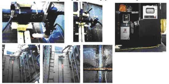 |
| Figure 6 Robots in action |
Visual inspections by qualified weld inspectors can be quite effective. The drawbacks include welding inspectors' varying skill levels and possible productivity slowdown. This is especially true on multipass welds, some of which require interpass inspection.
 |
| Figure 7 Weld quality results. |
Systems that can inspect welds visually during welding or immediately after and flag any defects now are available. These systems not only measure the weld's geometry, but also find and report defects, such as porosity and undercut. The inspection can be performed automatically by a portable robot or gantry robot system, or one can use a portable, hand-held gauge. Figure 7 shows a results screen that indicates defective welds and the reasons why they are defective. This information can then be used by the repair welder to locate welds that need correcting.
Another benefit of automatic inspection systems is their trending capability, which tracks defects and generates Pareto charts (shown in Figure 8, which can be used to identify which defects occur most often and the welding process's overall capability. This capability index can be used in the Six Sigma improvement effort.
Further improvements can result from the systems' ability to measure weld volume and geometry and identify how much overwelding—which can be expensive—is occurring.
 |
| Figure 8 Reasons for defective welds |
Products currently on the market can not only automate your welding operations, but also help you improve weld quality and productivity. You must look far upstream in your shipbuilding and other fabricating operations to identify variation sources that are affecting weld quality adversely. Only by knowing as much as possible about your operation can you identify the right opportunities for improvement.


The Fabricator is North America's leading magazine for the metal forming and fabricating industry. The magazine delivers the news, technical articles, and case histories that enable fabricators to do their jobs more efficiently. The Fabricator has served the industry since 1970.
start your free subscription
Easily access valuable industry resources now with full access to the digital edition of The Fabricator.

Easily access valuable industry resources now with full access to the digital edition of The Welder.

Easily access valuable industry resources now with full access to the digital edition of The Tube and Pipe Journal.

Easily access valuable industry resources now with full access to the digital edition of The Fabricator en Español.
In this episode of The Fabricator Podcast, Caleb Chamberlain, co-founder and CEO of OSH Cut, discusses his company’s...


